Chapter 2. Installation
OPTION SLOT ARRANGEMENT
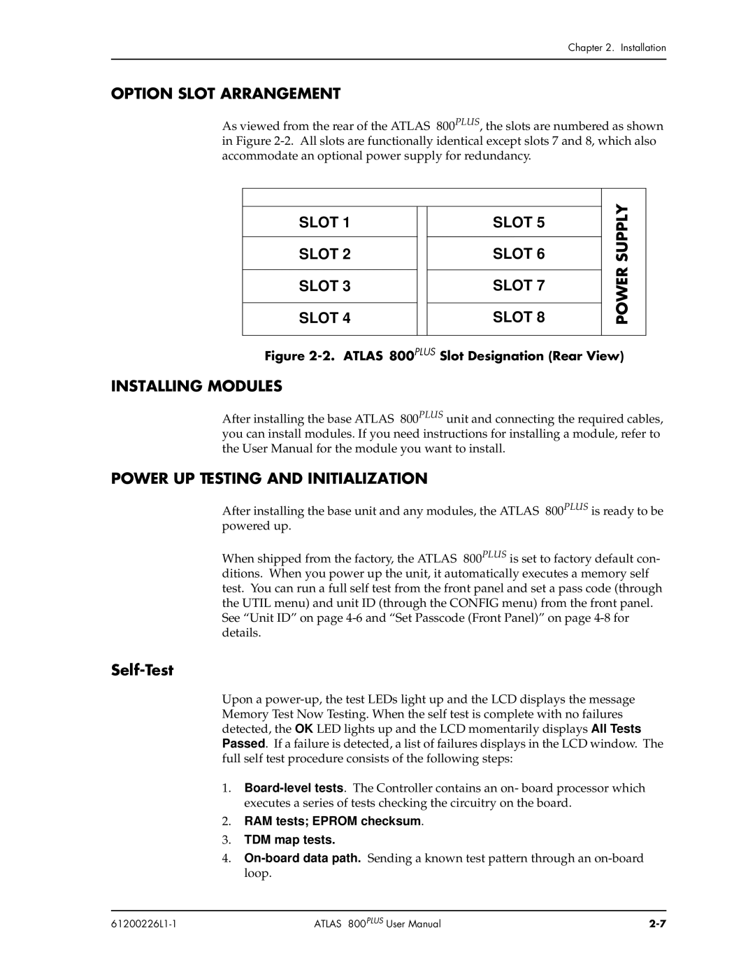
As viewed from the rear of the ATLAS 800PLUS, the slots are numbered as shown in Figure
SLOT 1
SLOT 2
SLOT 3
SLOT 4
SLOT 5
SLOT 6
SLOT 7
SLOT 8
POWER SUPPLY
Figure 2-2. ATLAS 800PLUS Slot Designation (Rear View)
INSTALLING MODULES
After installing the base ATLAS 800PLUS unit and connecting the required cables, you can install modules. If you need instructions for installing a module, refer to the User Manual for the module you want to install.
POWER UP TESTING AND INITIALIZATION
After installing the base unit and any modules, the ATLAS 800PLUS is ready to be powered up.
When shipped from the factory, the ATLAS 800PLUS is set to factory default con- ditions. When you power up the unit, it automatically executes a memory self test. You can run a full self test from the front panel and set a pass code (through the UTIL menu) and unit ID (through the CONFIG menu) from the front panel. See “Unit ID” on page
Self-Test
Upon a
1.
2.RAM tests; EPROM checksum.
3.TDM map tests.
4.
| ATLAS 800PLUS User Manual |