Chapter 7. Creating a Dial Plan
5.Select the Out (Outgoing) # Accept submenu. Enter $ in the number field. Leave all other selections set to default (Enabled).
6.Select the Out (Outgoing)# Reject submenu. Since no outgoing numbers need to be rejected at this port, no entry is required.
7.Select Interface Configuration (Ifce Config) submenu. Select the PRI switch type (National ISDN).
8.Press ESC to back out of the connection to the index number column.
9.Type I three times to insert another three connections in the list for the BRI lines.
10.Select Slot 1/ Port 1 for BRI A. Enter the Outgoing Accept and Reject numbers as in steps 5 and 6. The Outgoing Accept numbers have two entries:
11.This allows all numbers
12.Navigate to the Interface Configuration submenu. Select the BRI switch type the network is using (National ISDN). Descend into the SPID submenu and enter the SPID numbers and phone numbers which match the network provisioning for this BRI line.
13.Press ESC to return to the Index # column.
14.While on the entry for BRI A, type C to copy the entire BRI A entry.
15.Move to the next connection list entry and type P to paste all of the BRI data. Move to each field and modify as appropriate for BRI B.
16.Repeat 13 and 14 for BRI C.
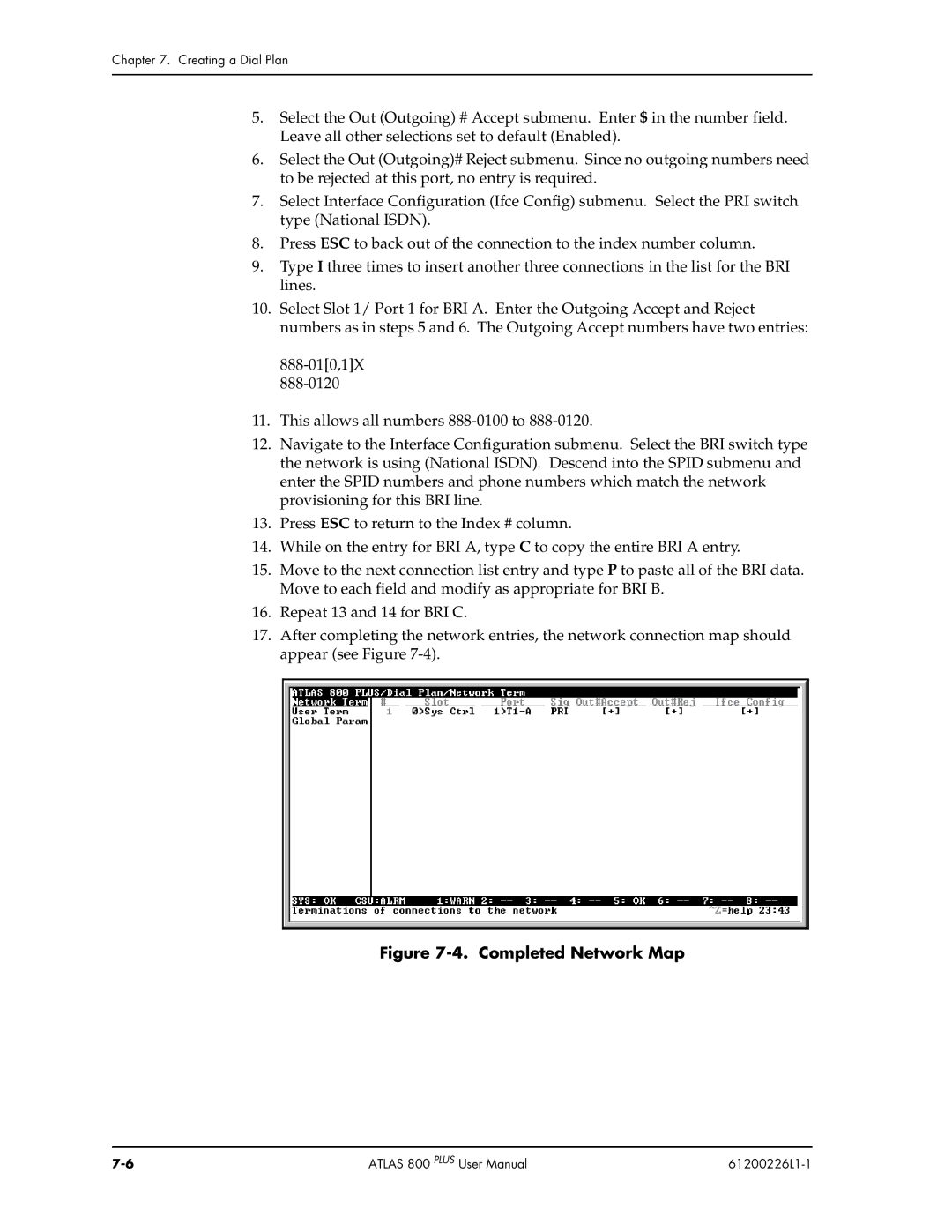
17.After completing the network entries, the network connection map should appear (see Figure
Figure 7-4. Completed Network Map
ATLAS 800 PLUS User Manual |
|