User’s Guide Agilent Technologies 8922M/S GSM Test Set
Agilent Part No January
Page
Contents
Screens
Keys
Connectors
Appendix a
Contents-6
Warranty
Responsibilities of the Customer
Restricted Rights Legend
Electromagnetic Compatibility EMC Information
Declaration of Conformity
Safety Information
Do not Operate in AN Explosive Atmosphere
Safety Symbols
ISM 1-A
Sales and Service Offices
Canada
Agilent Technologies 8922M/S Documentation Description
Typeface Conventions
Installing Your Agilent 8922M/S
Using this Chapter
Fuses and Power Cords
Voltage Selection Card and Fuse Installation Other Fusing
Line Voltage
Fuse Selection
Power Cords
Installation Overview
Rear View Connections
Access Config Screen
High-stability timebase set-up
General Information
Making Measurements
Making Measurements
Test Mode
Agilent Technologies 8922M/S Operating Modes
Active Cell
CW Generator
Agilent 8922M/S Operating Modes
Active CELL+ Test MODE+ CW GENERATOR+
Active Cell
Making a Call From the Mobile Phone to the Agilent 8922M/S
Active Cell Mode
Making a Call From the Agilent 8922M/S to the Mobile Phone
Shift , Cell Config MS Info
Changing Channel, Timeslot, and the Transmit Level
Mobile phone
Test Mode
Select Test Mode
Mobile Phone Receiver Testing Using Test Mode
CW Generator
Measurements
GSM Specific
Measurements
Ancillary Measurements
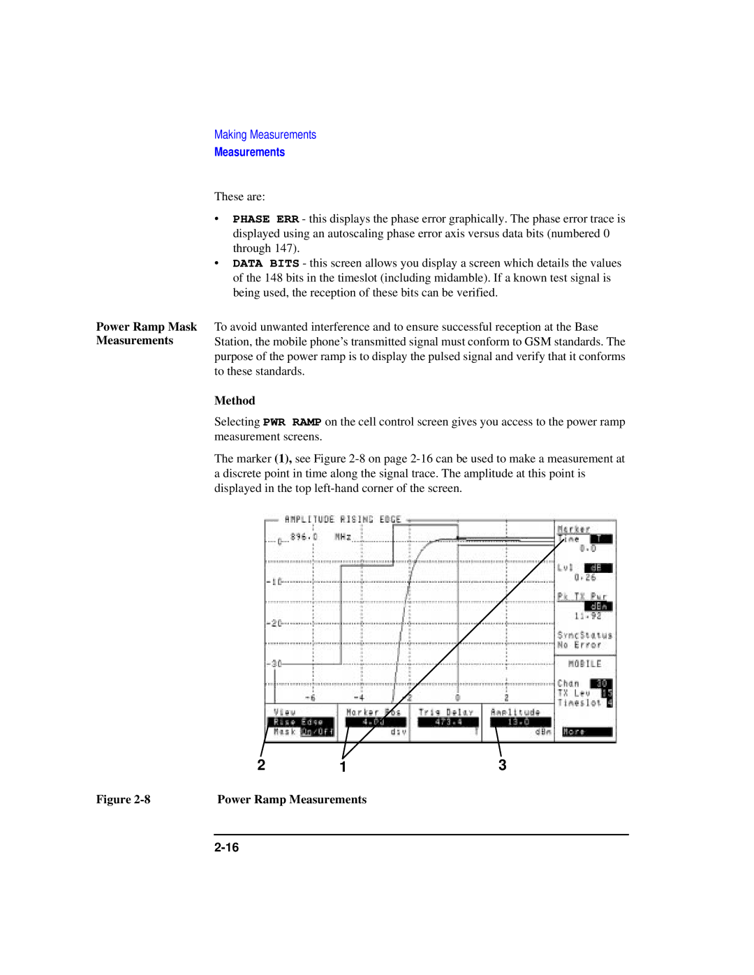
Method
Peak Power Measurements
Measurement
Phase
Frequency Error
Phase and Frequency Error Measurements
Measurement Method
Power Ramp Mask Measurements
Power Ramp Measurements
Measurement Summary
Failed
Passed
Blank field
Pulse Measurements
Bit Error Rate
Bit Error Rate Measurement
Measurements
31,4
Output RF Spectrum Measurements
Measurements
32 dB 51 dB 70 dB 39 dBm 27.5 37 dBm ≤ 33 dBm
Method
Spectrum Analyzer Measurement
Scope
Oscilloscope Measurements
Audio
Audio Measurements
CW Measurements
Out port
If You Have Problems with a Measurement
Is a Message Line displayed at the top of the screen?
If You Have Problems with a Measurement
Trigger Timing a
Trigger Timing B
Trigger Range For Pulsed RF
Is an Error Message Displayed in the Sync Status field?
Possible Solutions to Sync Status Errors
Solution 1 Trigger Timing
Solution 2 Midamble Sync
Solution 3 Level
Solution 4 Amplitude Envelope
If FM Errors
Advanced Features
Other Screens
⎛ RFin 20 ⎞
Advanced Features
Measurements Using
Making
Synchronized
External
Servlatchval
Unexpected
Operations
Advanced Features
Advanced Features
Advanced Features
Verifying Performance
About This Chapter
Setting up the Tests
Getting the Right Equipment
Equipment HP/Agilent Model Number
Installing and Operating the Software
To Load the Program Using Compatibility Switch
Understanding the Tests
Back Conversion
To Run the Program 1 Type RUN, press Enter
Forward Conversion
Gpib Addresses
Test 01 Signal Equipment Required Generator Level
Things To Check In Case Of Problems
Understanding the Tests
Theory of the Test
Test 02 Signal Generator Spectral Purity
Understanding the Tests
Test 06 Audio Equipment Required Frequency Analyzer
Test 07 Oscilloscope Equipment Required
Test 08 RF Analyzer Equipment Required Level
Test 09 RF Analyzer Equipment Required Gmsk Modulation
Test B Spectrum Analyzer Option 006 only Equipment Required
Test a RF Analyzer Equipment Required
Pulse Demodulation
Understanding Test Failures
Assemblies Tested P=Primary S=Secondary
GSM900 Functionality
Agilent Technologies 8922M/S Specifications
RF Generator Frequency Specifications
Output
SWR
Spectral Purity
Pulse Modulation
DB Pulse Modulation Agilent 8922M only
AM for Level Control Agilent 8922M Only
CW RF Frequency Measurement
RF Analyzer Frequency Specifications
CW RF Power Measurements RF In/Out Only
Pulse ON/OFF Ratio Measurement Requires Option
Peak/Transmitter Carrier Power Measurement
Power Measurement Accuracy
Inaccuracy due to Noise for overshoots ≤ 1 dB
Accuracy ON/OFF 40 dB, RF In/Out only
Amplitude Envelope Measurement
Phase and Frequency Measurements
Gmsk Data Recovery Agilent 8922M only
FM Demodulation Output Agilent 8922M only
Pulse Demodulation Output Agilent 8922M only
Dynamic Range dB
Spectrum Analyzer Specifications Option
Span Bandwidth
Output Level
Audio Source Frequency Specifications
Audio Analyzer Frequency Measurement Specifications
Distortion Measurement
AC Voltage Measurement
DC Voltage Measurement
Audio Detectors
Oscilloscope Specifications
Audio Filters
General Specifications
Remote Programming
Using both arms to lift instrument
Operating Environment
Tunable Reference Mode
Reference Specifications
Fixed Reference Mode
Agilent Technologies 8922M/S Specifications
Screens
Field Types
Data Entry
Field Types
Audio
Scope In selects the Scope in Measure front-panel
Meas Reset Meas Cntl Speaker ALC Speaker Vol
See Also Keys High LIMIT, LO LIMIT, AVG
Speech
Choices None
Selected measurement type
Bit Error
Results
CRC or FE
Res Type Measure
Control
Bit Error
This field is not featured in the Agilent 8922S
11/19. Ratio/Count
Ratios
Meas Cntl
Bit Error
Cell Configuration GSM
Arfcn
Field State
Amplitude
Aux Bcch BCC
Range Through
Control Ch
LAC
Range
10. MA1
11. MA2
MAIO1
MAIO2
MCC
Settable
Cell Configuration E-GSM, DCS 1800, PCS
Activated
Cell Configuration E-GSM, DCS 1800, PCS
BCC Base Station Colour Code is displayed in this field
Number 1 MA1
MAIO1
Cell Control Active Cell
Active Cell TestMode CW Generator
GSM/DCS1800/P
Only
Range GSM900
GSM
Call See Also Specifications
Range Through 6 , 1, and 7 are used for call maintenance
TX Level Mobile Timeslot Mobile
See Also Cell Control
Cell Control Active Cell +
Decode Errs
Single/Hop
Cell Control Test Mode
Choices GSM
DCS
PCS
Channel
TX Lev
Cell Control CW Generator
Shown will not correspond to the channel in amplitude
Single Other Settings
Cell Control
Caller
Call Status TCH State
Connect
DRX
DTX
Or off
Execute
Inactive Active Mode
19. MM
Loc Upd Ident Auth
Tmsi
Choices CCITT-15 2
CCITT-23
Reset Call
RACHs
Timing Err
Counts
Control Choices
Based on the TX Level field
Cell Control
Signaling Speech
Test
Mode Choices
Timeslot
Configure
Aux RF
Although a power cycle is recommended
Aux RF Out
O Config
Cntl
Offset
OPT
Choices 13 MHz 10 MHz
RF IN/Out
Service
Time
CW Freq, CWFreqErr
CW Measurement
Amplitude Expected Input
CW Power
Frequency Expected Input Meas Reset Meas Cntl
Cntl IN/OUT port when executing this function
RF IN/OUT
Fast Bit Error
Mobile
Burst Delay range 0 through
Configuration
Specification
Choices Bits
FF at Start
Form Feed
Inst Echo
Line Feed
Lines/Page
See Also Keys Print
Choices Serial
Parallel
Print Title
Stop data transmission from the computer to the instrument
Choices 300 600 1200 2400 4800 9600 19200 Serial
Ibasic control of the serial input port
Stop the instrument from transmitting to the computer
Logging
Measurement Sync
Be the lowest frequency Arfcn in the hop sequence
Burst Sel
Burst Used
Demod Arm
First Bit
See Also Screens Meas Sync Hopped TCH Arfcn Cntl
Midamble
To the selected Midamble or User Defined Sync Pattern
Trig Qual
Trig Delay
Sync Pattern Start Position
Message
MS Information / Signaling
Authentication Choices
Mode Applies if Special Option H05 is fitted
Implements the authentication algorithm specified in Rec
Ciphering
Imsi Attach/Detach
Last LAI
Location
MS Band
Capability
MS Revision
MS Imsi
MS Information / Signaling
BS Sres
Rand
MS Sres
Oscilloscope, Main Controls
Meas Reset
Controls
Marker
Time/div
Oscilloscope, Trigger Controls
Auto/Norm
Cont/Single
Level div
Pre-Trig
Screens
Oscilloscope, Marker Controls
Position
Marker To
Peak+
Sync Status
Output RF Spectrum, Main View Option 006 Only
Freq Offset
Output RF
Spectrum
Single/Cont
View
Output RF Spectrum, Trace View Option 006 Only
SyncStatus
Phase and Frequency Error Multiburst OFF
ON/OFF
OFF
Phase and Frequency Error Multi-burst on
Done
Errors
Peak Phase
Error Mean Maximum Minimum Last Peak phase
RMS phase
Burst Only Choices
Wanted
Marker Pos
Phase/Freq, Phase Err
Bursts
Frequency error
Phase/Freq, Data Bits
Polarity
Trg Timing
Pwr Ramp Rise Edge
Mask
Pk TX Pwr
Pwr Ramp, Top 2 dB
Pulse Puls Rise Puls Fall
Pwr Ramp, Fall Edge
100
Pwr Ramp Summary
Ampl1-12
Power over the useful bits in the measured burst
Flatness
Summary
Time1-12
103
Pwr Ramp Pulse Option 006 Only
Fall Pos
Rise Pos
See Also Making Measurements Solving Problems Messages
Meas Sync Sync Status
106
Pwr Ramp Pulse Rise Option 006 Only
MarkerPos
POnOffRise
Pwr Ramp Pulse Fall Option 006 Only
POnOffFall
RF Generator / RF Analyzer AF Gen
Accuracy
AGC Mode
RF Generator / RF Analyzer RF Analyzer
Hop Mode
Hop Offset
Range RF Input
Hop Trig
Value
DAC Value
RF Generator / RF Analyzer RF Gen
Atten Hold
Hop Mode Hop Trig
DC AM Frequency
Gmsk
Range 10.0 to 1015.0 MHz
Pulse
RF Output
Service
Code
Default for message 2 is
SMS Cell Broadcast
Language
Message Broadcast
121
Spectrum Analyzer, Main Controls Option 006 Only
Max Hold Meas Reset
Center Freq
Ref Level
Span
Spectrum Analyzer, RF Gen Controls Option 006 Only
Spectrum Analyzer, Marker Controls Option 006 Only
Center Freq Marker To Next Peak Marker To
Range To 10 divisions
Spectrum Analyzer, Auxiliary Controls
Auto Hold Input Atten
10 dB 20 dB 30 dB 40 dB
Video BW
DB Input Atten Choices GSM900 GSM, DCS 1800
Tests
130
Keys
Key Map
Cancel
Function Keys
Adrs
Assign
Hold
END Call
HI Limit
Incr SET
LO Limit
To Set a Low Limit
To Turn Off or On a Low limit
Print
Meter
MS Info
To Recall an Instrument Setup
Recall
REF SET
Certain value
To Set a Reference
To Turn a Reference Off or On
To Save an Instrument Setup
RFG/RFA
Save
Tests
Local Keys
L1, L2
That is currently displayed
To Assign a Local Key
Global Keys
To Assign a Global Key
Units Keys
Connectors
Front-Panel Connectors of the Agilent Technologies 8922M/S
See Also Screens RF Generator/RF Analyzer, RF Gen
Clock Demodulation OUT
Agilent 8922M Only
Clock Modulation Agilent 8922M Only See Also
Clock Input
Data Demodulation OUT
Requirements
FM Demodulation OUT
AM/SPEECH Modulation Agilent 8922M Only
Screens Audio Audio In Lo
Modulation
Monitor Demodulation OUT
Pulse Demodulation OUT
MON/SPEECH Agilent 8922M Only
Audio OUT
Pulse Modulation Agilent 8922M Only
Measure
Trigger in Measure
Valid Demodulation OUT
Rear-Panel Connectors of the Agilent Technologies 8922M/S
See Also Specifications REF
Emmi BUS Agilent 8922M Only
Pin Usage Function To/From
Electrical Characteristics of the DAI/EMMI
Emmi Connector Pin Numbers See Also
Logical State Voltage Current
Gpib
General Purpose Agilent
OPT 001 REF OUT
131
Scope
Specifications
Signal Descriptions for System BUS
DEMODDATA, Demodclk Demodvalid
Fpdata
Fpclock
Gexttrig
Pulsemodin
Pin 6 Input
RPBURSTT1
T1-Pin 26, T2-Pin 8 Select/Control
Rpdmodtrig Pin 7 Input
Rpgsmrstin
Pin 3 Input
Rpgsmrst
RPHOPADRS0, through RPHOPADRS9, RPHOPADRS10
Rphopinhibit
Pin 30 Input
Rprstseq
Pin 11 Input
Rprxhop
Pin 10 Input
Rpseqhop
Pin 29 Input
Seqtrigout
RPTXD, Rprxd
Rptxhop
Input
Usememextt 27 Pin Input
RIG
Timing Diagrams
Digital Demodulation Timing Specification Table
Digital Demod Timing Diagram
Frequency Hop Timing Specification Table
RF Generator Hop Address Source = Ext Timing Diagram
RF Analyzer Hop Address Source = Ext Timing Diagram
RF Generator Hop Address Source = Int Timing Diagram
RF Analyzer Hop Address = Int Timing Diagram
Reset Hop Once Address Source = Int Timing Diagram
Reset and Hold Hop Address Source = Int Timing Diagram
Hop Inhibit Address Source = Int Timing Diagram
Messages
Communication Failures
Firmware Error
Firmware revision error in module
Sync Status
Protocol Error Messages
Timers
Following is a brief description of the timers
Call Control Timers
Timer Values
Data Link Layer Disconnects
Disconnects
Physical Layer Disconnects
Layer Disconnects
Management Layer
Disconnects
Call Control Layer Disconnects
Host I/O Error Operating System Error Unknown Errors
Protocol Log Examples Of Typical Calls
Monitoring For Protocol Failure And Recovery During Test
Instrument Basic
Ibasic
Agilent Technologies 8922M/S Instrument Basic Overview
This Chapter Tests Subsystem
Programs That Use the Tests Subsystem
Programs That Do Not Use the Tests Subsystem
Configuration and Instrument Control
Controlling HP 8922M/S Functions Connected Instruments
Hardware Connections Agilent 8922M/S Configuration
For Programming
Serial Port Connections
Serial Port Configuration for Programming
Connecting the Serial Port
Configuring
Configuring an IBM-Compatible PC With HP AdvanceLink
Set Parity to none
Set Data Bits to
Set the Global Configuration settings
Verifying Serial Port
To Ibasic
Operation
Controller screen
Loading, Storing, and Running
Storing an Ibasic Program On a Gpib Disk Drive
Running Your Program Loading a Test Procedure
Storing Ibasic Programs On Memory Cards
Loading, Storing, and Running
Test Procedure Files
Making or Deleting
Test Procedure and Test Library Files
Sequence
Making a Test Procedure File
Running a Test
Accessing the Agilent Access the Tests screen by pressing
Entering and Editing Programs
8922M/S’s Ibasic
Controller
Using HP-IB
PROGram Interface Commands
Other Prog Commands
Download Program for Computers using Gpib
Preparing the Agilent 8922M/S to Receive Programs
Downloading a Program Into the Agilent 8922M/S
Entering Commands
Line-by-line Entry and Editing
Using Memory Cards
Memory Cards
Memory Card Part Numbers Type
Inserting a Memory Card
Types of Memory Cards
Initializing an Sram Memory Card
Initialize Internal
Setting the Write-Protect Switch
Setting the Sram Write-Protect Switch
Procedure for Backing Up a Memory Card
Backing Up the Memory-Card Programs
Filenames are prefixed with a lowercase l
Memory Card Battery
Replacing the Memory-Card Battery
Contaminate battery contacts in the memory-card
To the manufacturer’s instructions
Programming and Using the Tests Subsystem
Procedure Files
Tests Subsystem File Descriptions
Code Files
Main Tests Subsystem Screen
Tests Subsystem File Relationship
Tests Subsystem
Programming and Using the Tests Subsystem
Program Status
Setting Up the Test Execution Conditions
Ibasic Programming
To Continue or Pause After Each Test
To Have Testing Stop or Continue on a UUT Failure
Test Execution Conditions
To Enter Comments in the Output Heading Field
To Select Printing Conditions
To Have Test Results Appear on a CRT or Printer
Making a Test Sequence
Using Autostart
Tests Screen of the Agilent 8922M/S
Editing Test Specifications
Test-Sequence Screen
Chapter, select the following keys
Edit Sequence Screen on the HP/Agilent
Editing Test Parameters
Configuring External Instruments for Gpib Control
Edit Parameters Screen on the HP/Agilent
17 on
General Organization
Instrument-Configuration Screen
Program Structure for Tests Subsystem Programs
Program Example
Program Listing
RUN Through the Sequence of Tests
Test
Linenumber Command Description
Program Listing Explanation
Programming and Using the Tests Subsystem
Programming and Using the Tests Subsystem
Creating a Library And Default Procedure File
Creating a Procedure File With No Library
Appendix a
Purpose
Equipment Required
Connecting the Agilent 8922M to the HP/Agilent 37900D
Figure A-1 Cabling Setup Front View
Latch
Setting Up the Agilent Technologies 8922M
Camp On
Setting Up the HP/Agilent 37900D
Card
SLP
Connection
How to Obtain a Protocol Log
Check
Logging
Start-up
Make Call
Real Time
System
Information sent
Received
End Call
Additional Information
Remote Control of Protocol Logging
Protocol Log of a Typical Call
Primitive
Protocol Log of a Typical Call
PH-DL Phdata Sdcch UI P0 CR0 SAPI0 M0 Frame
MM-CC Mmdata CC Call Confirmed 83 08 Frame
Command Frame
MM-RR Rrsync Frame
Frame
DL-PH Phdata Sdcch I Nr1 Ns1 P0 CR1 SAPI0 M0 RR Assignment
DL-RR Dldata Facchf CC Alerting 83 41 Frame
DL-RR Dldata Facchf CC Connect 83 07 Frame
DL-RR Dlrelease Facchf Frame
Call setup is complete
Goes to NEW TCH2
Inter-cell handover to TCH1, Single TCH on Arfcn 30, slot
Intra-cell handover is complete
Agilent 8922M/S configures to new
TCH
DL-RR Dldata Facchf RR Handover Complete 06 2c 00 Frame
Inter-cell handover complete
Call termination
2449761
Port Frame
CC-HST Ccrelind Frame PH-DL Readytosend Facchf Frame
Protocol Log of a Typical Call
Glossary
Arfcn
CRC
Gmsk
Rssi
Glossary
Index
Index-2
Index-3
Index-4
Index-5
Index-6
Index-7
Index-8
Index-9
Index-10
Index-11