3. Installation
Signal Installation
páÖå~ä=fåëí~ää~íáçå
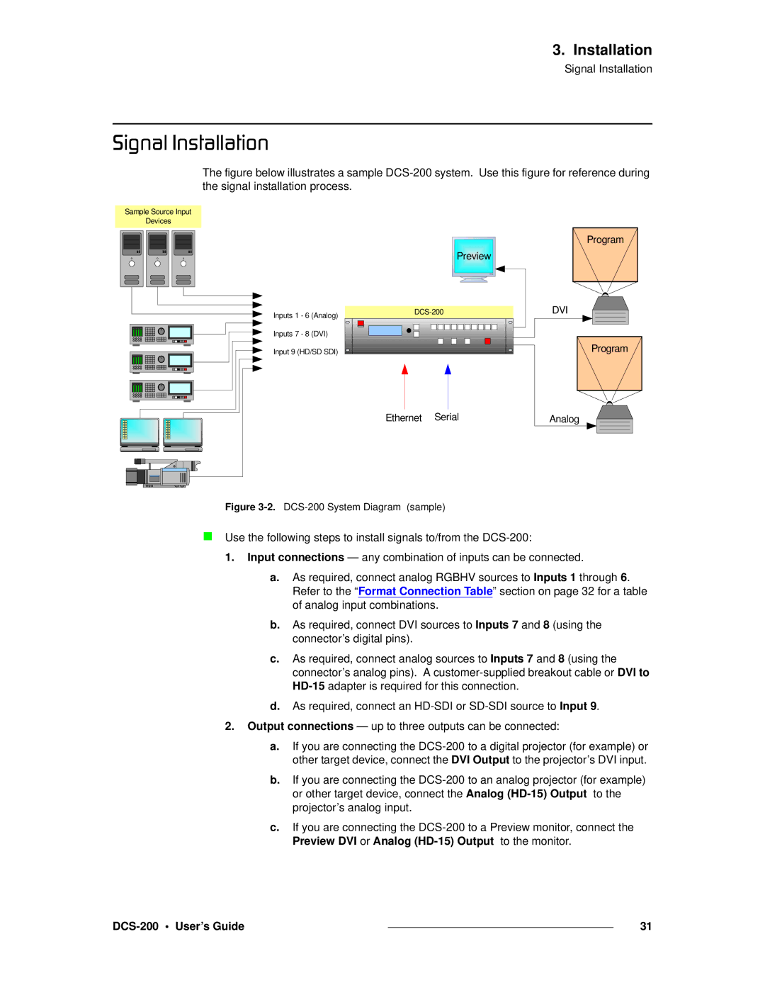
The figure below illustrates a sample DCS-200 system. Use this figure for reference during the signal installation process.
Sample Source Input
Devices
Preview |
Inputs 1 - 6 (Analog) |
Inputs 7 - 8 (DVI) |
Input 9 (HD/SD SDI)
Program
DVI
Program
Ethernet Serial | Analog |
Figure 3-2. DCS-200 System Diagram (sample)
Use the following steps to install signals to/from the
1.Input connections — any combination of inputs can be connected.
a.As required, connect analog RGBHV sources to Inputs 1 through 6. Refer to the “Format Connection Table” section on page 32 for a table of analog input combinations.
b.As required, connect DVI sources to Inputs 7 and 8 (using the connector’s digital pins).
c.As required, connect analog sources to Inputs 7 and 8 (using the connector’s analog pins). A
d.As required, connect an
2.Output connections — up to three outputs can be connected:
a.If you are connecting the
b.If you are connecting the
c.If you are connecting the
|
| 31 |
|