FM-3 Programming Module Reference Manual
Figure 50: Input Line Diagram
If the Input Line attached to the home sensor is debounced, the actual rising edge of the Home Sensor is used to determine the Home Reference Position (the debounce time ensures a minimum pulse width).
Output Lines View
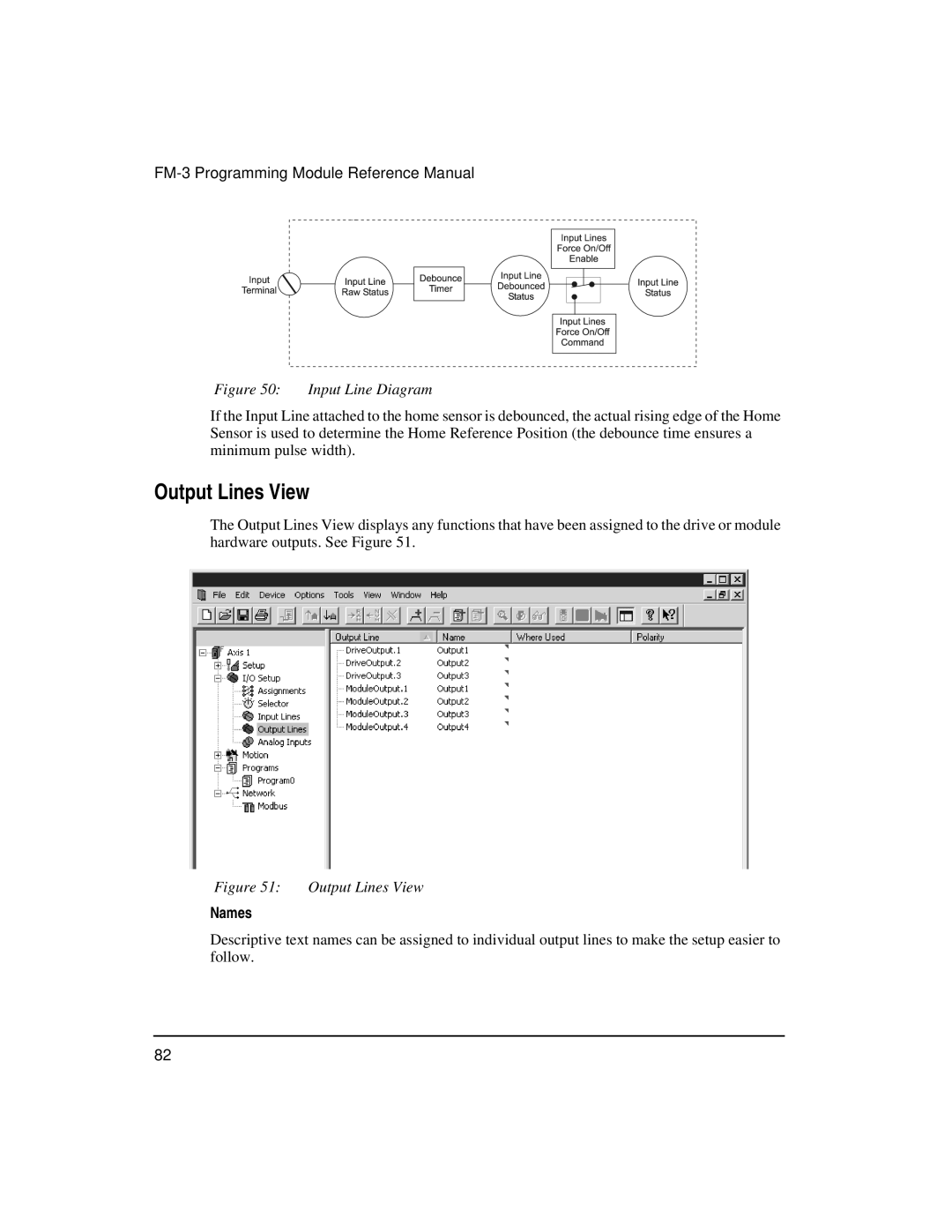
The Output Lines View displays any functions that have been assigned to the drive or module hardware outputs. See Figure 51.
Figure 51: Output Lines View
Names
Descriptive text names can be assigned to individual output lines to make the setup easier to follow.
82
