Epson Stylus Pro 7600/9600
Page
Precautions
About This Manual
May 10 First release
Revision Status
Contents
Operating Principles
Troubleshooting
Disassembly & Assembly
Adjustment
Appendix
Maintenance
Product Description
Throughput Stylus Pro
Features
Epson media Quality Resolution Mode Throughput Dpi
Product Description
Stylus Pro
Differences between Stylus Pro 7600 and Stylus Pro
Differences between Stylus Pro 7600 and Stylus Pro
Control Code
Basic Specifications
Print Specifications
Character Specification
Plain Paper
Paper Specifications
Roll Paper
Acceptable Paper
Paper Size Size W ⋅ H
Sheet
Borderless Print Roll Paper
Acceptable Sheet Sizes Acceptable Paper
Description of units of measure
Borderless Print Width
11. Availability with Special Paper Pigment
Special Paper
† Roll pigment
12. Availability with Special Paper Dye
† Roll dye
13. Availability with Sheets Pigment
† Sheet pigment
15. Printable Area
Mechanism Specifications
Roll paper Model Dimension Sheet
Printable Area
Manual Cutting of Roll Paper
Cutting Specification
Paper Set Lever
Automatic Cutting of Roll Media
Reliability
Electrical Specifications TBD
Vibration
Temperature/Humidity
19. Temperature/Humidity
Ambient Conditions
Stylus Pro 7600 with stand/ Stylus Pro
Surrounding Space
Stylus Pro 7600 without stand
† Dimensions of Unit
Overall Dimensions
Model Condition Weight
Name Model Number Ml Standard Product
Accessories
Accessories and Options for Stylus Pro
Name Model Number Ml Standard Product 220ml Option
External View
External View and Parts Names
Operating panel contains the following buttons
Operating Panel
Buttons and Functions
Functions of Buttons
LED color Display Printer Status
LEDs
21. LEDs
Indications on the Panel
LED Indications in Normal Mode
Functions LCD panel display Indicator
LCD Indications in Normal Mode
27. Indications in Normal Mode
Functions LCD panel display Indicator Setting
Outline
SelecType
28. Panel setting menu item
Panel Setting Menu Item
Inkleft
See BK ink cartridge replacement
Paperthkns
Command
PG Setting
29. PG Setting Values
Paper thickness Panel SN command Actual PG
Roll Paper Margin
Code Page Switching
Lines
Interface Select
Detect Paper Width
Detect Skew Error
Job Timeout Setting
No margin mode Right/left no margin Sides no margin
No margin print setting
† No margin setting
Mode Operation
„ Number in print pattern and cutter position
Cutter position adjustment
† Level structure of Cutter position adjustment menu
Auto margin refresh
Value of ddddd.d-eeeee.e 5.1 figures
Panel Setup Value Initialization
Setting item After initialization
Nozzle Check Pattern Printing
Status Printing
12. Status Sheet Print Pattern
13. Job information print pattern
Job Information Print
Ink remaining
Maintenance tank count
Firmware version
Printable pages of each ink cartridge
Job history clear
Use counter
Clear use counter
Job history display
These indications
Consumables life
36. Reference value
Display Life
Epson Stylus Pro 7600/9600 Revision a
Suction LCD display
Load Paper Suction
Status LCD panel display
† Printer status at indicator display
† Ink remaining display and font
Ink type Panel display position
Information Explanation Range Capacity
Job information
37. Job information
Paper setup Operation
User Paper Setting
Paper setting and corresponding operation are as follows
Details of each setting item are following
15. Level Structure of User Setting Menu
Print Paper Thickness Detection Pattern
† Printing Specifications
Top pattern
Pattern Displacement Bottom pattern relative to
Number
Gap Adjustment Bi-D Adjustment, Uni-D Adjustment
Power cleaning
Cutter Blade Replacement
STD
Paper thickness sensor PG setting Saving place Setting
18. Level Structure of Gap Adjustment Menu
45. Adjustment Item List
GAP Adjustment Print Pattern TBD
„ Each adjustment item
Release INK Lever
BK ink cartridge replacement
Replace with NEW Maintenance Tank
LCD panel message Insert ALL INK Cartridges
Insert Draining Cartridge in #X
LCD panel message Insert Cartridge in Correct Slot
LCD panel message Remove Draining Cartridge
Outline
Maintenance Mode
Maintenance Mode 1 Setup Items
46. Maintenance mode 1 setup items
Expir Date M
Panel Display Language Selection
Hexadecimal Dump
INK Information Menu
Parallel I/F Mode
Setting D4
Unit Change
Maintenance Mode
48. Maintenance mode 2 setup items
Maintenance Mode 2 Setup Items
For R4C825P
Cleaning times TCL2
Top menu Panel display Item menu 1 Panel display Setup value
Each color ink replacement date Black2, 2 times before
Each color ink vendor Yellow, this time
Menu Print length of each paper size Roll paper width
Print mode setting times 360-720 Bi-D
Black
Menu Service call history6 Type
Normal error Menun Normal error history 6 Type
Initinfo
Maintenance Information Menu
Initialize NVRAM, TIMER, Life COUNTER, Mechanical Counter
Initialize Cleaning Unit Life
Parameter Backup
† User table initialization
Paper feeding adjustment conversion table
† How to change correction values
System table
Firmware Reload
Reload with F/W Download mode
Installation with service utility F/W Update function
Compulsory start F/W Download mode
Software initialization
Function to prevent irregular printing
Initialization
Hardware initialization
Ink Type Setting
Default Setup Values
Initial Setting for Operation
Esck Escd
MW Printing Adjustment / Setting Values and Printing Modes
Valid print mode combination is following
Printing Mode Combination Table
Controller
Interfaces
Compatibility Mode
Specification
Connector PIN Assignment and Signals
Parameter Minimum Maximum
Parallel Interface Timing Chart
MDL Stylus Pro 7600-DYE/Stylus Pro 9600-DYE
Nibble Mode
55. Connector Pin Assignment and Signals Nibble
Pin Return Signal Name In/Out Function
56. Connector Pin Assignment and Signals ECP
ECP Mode
MDL Stylus Pro 7600-DYE/Stylus Pro 9600-DYE CLS
57. Connector Pin Assignment and Signals Usbfs
USB interface
CMD
Reply Message
Reply for Option Command
Optional Interface
Type-B interface level 2, 1200mA type is supported
Prevention Hosts from Data Transfer TIME-OUT
Supported Main Command and Sending Timing
59. Commands and Sending Timing
Supplements
Ink Cartridge
Installation Locations
Optional Units and Consumables
Draining cartridge
Cleaning cartridge
Maintenance Tank
Cleaning cartridge is the same as the 220-ml ink cartridge
Operating Principles
Explanation is composed as follows
Overview
Printer Mechanism Components
Print Mechanism Components
Carriage Mechanism
Carriage CR Mechanism
Assembled to the nearest 1/100 mm at the factory
Carriage Moving Unit
Ink Type Nozzle Row Color
Print Head
Relationship between Nozzle Rows and Colors
Printing Modes Drive Waveforms
Carriage Mechanical Unit and PG Adjustment Unit
Platen GAP Adjustment Unit
Position Gap Width Application Pulse Count from
Pulse Positions
Platen
„ It must be ensured that the reflection value of the least
Reflective paper is greater than the reflection value
Operating Principles Print Mechanism Components 109
Is not made by the edge sensors
„ Paper size detection sequence front edge
Conditions
Operating Principles Print Mechanism Components 111
Operating Principles Print Mechanism Components 112
11. Paper Feed Mechanism Unit 1/2
Paper Feed Assembly
13. Paper Feed Mechanical Unit Stylus Pro 7600 2/2
Modes
Pump Drive Modes
Cleaning Mechanism
Operation Explanation
Explanation of Operation
16. Valve Mechanism
Ink Supply Mechanism
Cover Sensor
Circuit Board Placement
Others
SD-RAM
Outline of Control Circuit Board
Major Elements
Name/Code Location Function
Input Voltage Range V AC Fuse Rating 100 +/- 10% AC / 6.3A
Outline of Power Supply Circuit Board
Signal Name Function
Fuse Rating
Troubleshooting
Introduction
Outline
Error Indications on LCD
Error Display
Errors
Error Indications on LCD
Full
Maintenance Tank Almost
Error Code Description Refer to
Service Call Fatal Errors
Service Call Fatal Errors
Paper set lever is released during operation
LED Indications for Wrong Setting Roll Paper/Sheet
Paper End/End of roll
Wrong paper source is selected on panel
Front Cover Open
Paper set lever is released
Paper Jam
Paper Not Straight
Type-B I/F error
Paper cutting error
Not enough ink for cleaning
Paper check error/Paper eject error sheet
Paper is too thick for cleaning
Ink lever released
Ink-related Errors
Defective ink cartridge
Illegal ink cartridge
Maintenance tank full
No Maintenance tank
Fatal Error
Bit Request object Cause How to recover errors
Troubleshooting for Warning
Maintenance tank full warning
Maintenance request
Clear Counters / RTC
Assigned bit Nnnn Cause How to clear
Rsvd
Motor
CR motor life
Troubleshooting for Service Call Errors
„ When the CR motor has still an adequate life remaining
Replace the PF Motor p.185
PF motor encoder check error
PF Motor out of step
PF motor in-position time out
PF motor overcurrent
CR motor out of step
CR motor encoder check error
CR motor in-position time-out
CR motor overcurrent
System interrupt watchdog time-out
CR home position sensor error 0001000A
PF home position sensor error 0001000B
Servo interrupt watchdog time-out
CR motor PWM output faulty 0001000F
Head slide PG home position sensor error 0001000C
Head driver TG temperature error 0001001B
PF motor PWM output faulty
Clear the cause of paper feed related mechanism out-of-step
CR servo parameter error 0001001D
PF servo parameter error 0001001E
RTC analysis error
Csic reed/right error
Ink type error setting on printer body side
CR Asic ECU error 0001002A
Csic ROM communication error
RTC communication error
Head error
Program load error 0002000A
Sdram error
Flash memory SUM error
Boot program SUM error
CPU address error storage misalignment
Review error 0002000C
CPU slot illegal command exception error 100001A0
CPU address error load misalignment 100000E0
Dot Missing
Troubleshooting Based on Your Printout
Smudged or Marred Printout Front
Uneven Printing/Poor Resolution
White or Black Banding in the carriage running direction
Smudged or Marred Printout Reverse side
Banding in the paper feed direction
Disassembly & Assembly
Summary
Precautions
Edge in the printer mechanism
Manufacture. Dispose the used batteries according to
Governments law and regulations
Immediately
Disassembly & Assembly Summary 154
Following table lists all the screws used in this printer
Tools
Screw List
Necessary Tools
Refer to -2when determining the disassembly flow
Disassembly Flow
Disassembly & Assembly Summary 157
Housing Part Diagram
Removing the Panel Unit and Housing
Panel Unit Removal 1/2
Panel Unit
R Side Cover Removal 1/5
Side Cover
R Side Cover Removal 3/5
R Side Cover Removal 4/5
11. L Side Cover Removal 1/2
13. I/H Cover Removal
4 I/H Cover
14. H Top Cover Removal on left side
Top Cover
Rear Cover
„ Removing and installing the Rear Cover
Loosen the screw Main Board Access Cover Remove the screw
18. Paper Guide L2 Removal
Paper Guide L2
20. Roll Paper Cover removal
Roll Paper Cover
Opens and closes
Front Cover
Print Head
Disassembly and Assembly of Carriage CR Mechanism
Procedures are required
When replacing the print head, the following adjustment
Will be expelled, so do not press on this part
Damper Assy
Execute ink discharge Ink Blowing before removing
Damper Assy
CR Board Assy
Connectors on CR Board
Connector Type Connected to
Cutter Section Cutter Holder Assy
33. Removing the Cutter Housing
35. Take Care When Installing the Cutter Holder
36. Cutter Solenoid Removal
Cutter Solenoid
Made
CR Encoder Sensor Assy
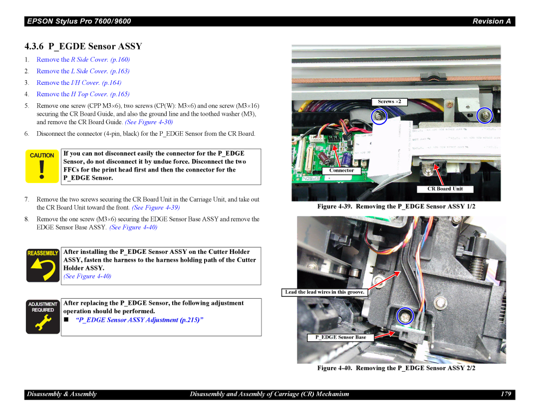
Operation should be performed
After replacing the Pedge Sensor, the following adjustment
Pegde Sensor Assy
CR Motor Assy
41. Indicator Position
43. Removing the CR Motor Assy
CR Motor, make the following adjustment
44. Removing the Headslide Sensor Assy
Headslide Sensor Assy
46. Releasing the Crhp Sensor Assy Harness
Crhp Sensor Assy
Fastening Spring on the L Side Frame side
CR Encoder Scale Timing Fence
PF Motor
Disassembly and Assembly of Paper Feed Mechanism
PF Encoder Sensor Assy
Adjustment
53. #F730 tool and PF Loop Scale Base
Assembly Procedure for the PF Loop Scale Assy
55. Affixing the Double Sided Tape to the PF Loop Scale
PF Loop Scale Assy Affixing Procedure
57. Suction Fan Mounting Position
Suction Fans
† Pthick Sensor Assy † PTHICK0.3 Sensor Assy
Adjustment at reassembly
Pthick Sensor/PTHICK Sensor0.3 Assy
Window
Prear Sensor Assy
1 C472SUB-B Board
Disassembly and Assembly of Ink Supply Mechanism
Discharge
When removing and installing the front cover switch holder,
Following adjustment should be made
2 I/H Ink Holder Assy
65. I/H Frame Removal 2/2
67. Csic Relay Board Removal
69. Disassembling the Ink Holder Assy 1/2
Front Cover
Cover Sensor Assy
Cover Sensor Assy operates coupled with the opening/closing
Names of Parts See
Disassembly and Assembly of Cleaning Mechanism
Major Parts of Cleaning Mechanism
Carefully so that ink will not spill
Maintenance Assy Removal
When you replace the Maintenance ASSY, ink can spill from
Disconnect the connector CN17 of the Pump Motor Assy
Cap Assy
Pump Motor Assy
Counters See p.71
Pump Assy
Once you have replaced the Pump ASSY, execute Clear
Spring catch
78. Removing the Cleaner Head
Cleaner Head Wiper
79. Removing the Flushing Box Assy
Flushing Box Assy
Connectors on Power Supply Board
Disassembly and Assembly of Circuit Boards
Power Supply Board
Power left in the boards capacitors
81. Removing the AC Inlet Holder
AC Inlet
83. C472MAIN Board Removal
Main Board C472 Main
CN.No Pins Color Connection Remarks
† Main Board Connector List
Jumper Setting at Factory at Shipment
DIP Switch and Jumper Setting at Factory before Shipment
Changing their setting can result in malfunctions
DIP Switch Setting at Factory at Shipment
Adjustment
MCSP24R4
Adjustment Tools
Adjustment Tools
Name Part Code
Print Head Adjustment
Procedure for Adjustment Work
Adjustment Items
Main Board Adjustment
Power OFF → Paper Feed ∆ +Paper Feed ∇ + Cut/Eject
CR Motor Adjustment
PF Motor Adjustment
Required Adjustment Items CR Motor Replacement
CR Encoder Sensor Assy Adjustment
Pedge Sensor Assy Adjustment
Prear Sensor Assy Adjustment
PTHICK/PTHICK0.3 Sensor Assy Adjustment
12. Required Adjustment Items
Cover Sensor Assy Adjustment
PF Encoder Sensor Assy Adjustment
11. Required Adjustment Items
Battery
Cutter Solenoid Assy or Paper Guide L Adjustment
Damper Assy Adjustment
Release Sensor I/H Lever Adjustment
Others
Parameter Backup
Parameter Backup Procedure
Work Procedure
Check Set the parallel interface in the compatibility mode
Firmware Reinstallation
Firmware Installation through ROM-DIMM
Firmware Installation through Interface
Overview
Self-diagnostic Function
How to Start Self-diagnostic Function
15. Key Functions in Self-diagnostic Mode
Top Menu
16. Self-diagnostic Function List
Description See
Test
Test is intended to check the circuit boards
17. Circuit Board Check Items
Control Panel
Version
Menu Transition of Sensor Test
Sensors
Check to see if each fan operates. See Figure
Encoder
2.5 Fan
Record
Maintenance Record
Csic
Record of Errors
Internal information on Csic is displayed
Internal Information Display of Csic
Automatically move up
Actuator
You can operate actuators. See Figure
Cutter
19. Panel Setting Item List
Adjustment
Power OFF → Paper Feed ∆+Paper Feed ∇+Cut/Eject → Power on
Rear AD Adjustment
Adjustment and Checking Procedure
Start the Self-diagnostic Function
„ Paper to be used A3 plain paper
Edge AD Adjustment
Input Rank
Damper ASSY, select and execute Initial charge in Cleaning
22. Menu Transition of Panel Input
Input Line Selection
End
† Dye code input
This mode, input a dye code by operating on the panel
Right
Write D/A Value
4BUTWTU
Check Nozzle
20. Pattern
Pattern Description
Check Skew
Feed Correction + T&B Adjustment
Coordinate in units of 360 dpi
21. Positions where Vertical Line Patterns Are Drawn
To be placed
Feed Correction + T&B Adjustment
Display Adj Feed Adj.+T&B
Paper Feed ∇ → SelecType → Paper Feed ∆
34. Menu Transition for Top & Bottom Adjustment
Top & Bottom Adjustment
Display Adj Rear Sensor Pos
Rear Sensor Position Adjustment Procedure
Rear Sensor Position
Display Adj Sponge Pos
Platen Position Sponge Position Adjustment
Platen Position Sponge Position Adjustment Procedure
40. Menu Transition for Platen Position Checking
Platen Position Checking
Check the print result to see if the head is slanting
† Adjustment Range 38 steps
Head Slant Checking
Lever Up Magenta → lower / Black → rise
Head Slant Checking Procedure
Head Slant Adjustment Mechanical Adjustment
Head motion by Head Adjustment Lever operation
Contents
Round Trip Print Position Adjustment Bi-D Adjustment
22. Adjustment Item List
SelecType → SelecType → Enter
BI-D Adjustment Procedure
† K Black Line Adjustment Procedure
Display Adj Bi-d
Adjustment Self-diagnostic Function 250
Parameter Copying
Bi-D2 Adjustment PG=0.7mm
Bi-D3 Adjustment PG=2.1mm
52. Menu Transition for Bi-D Adjustment Checking
Round Trip Print Position Bi-D Adjustment Checking
Correct the print position for one-way printing
Head Gap Adjustment Uni-D Adjustment
23. Head Gap Adjustment Items
Therefore, there is no need of outputting the comprehensive
Procedure for Head GAP Adjustment UNI-D Adjustment
† If out of alignment
Display the menu for an relevant item by means of SelecType
56. Menu Transition for Test Pattern Printing
Test Pattern Printing
57. Menu Transition for Head Cleaning
Clean Head
Counters to be Cleared Initial Value
Counter Clear
24. Counters to be Cleared and Their Initial Values
Adjustment Self-diagnostic Function 258
Charge in this menu
Cleaning
25. Cleaning Items
Print
27. Parameter Items
Parameter
With the condition of the printer mechanism
Parameter Initialize
Execute parameter initialization
Adjustment Self-diagnostic Function 262
29. Required Mechanism Adjustments
Mechanism Adjustment
CR Timing Belt Tension Adjustment
65. PF Belt Tension Adjustment
PF Timing Belt Tension Adjustment
Display Sen Paper
PTHICK0.3/PTHICK Sensor Mounting Plate Position Adjustment
Display Test Sensor
SelecType → Paper Feed ∇
LCD
Mounting Plate Gauge Condition
Display Sen Cover
Cover Sensor Assy Mounting Position Adjustment
31. Cover Sensor Assembly Check
Sensor is installed correctly and check the operation again
Mounting jig designed for any other printer models
CR Encoder Sensor Mounting Position Adjustment
Use with Stylus Pro 7600 / 9600 do not use the CR Encoder
Cutter Holder Assy height adjustment
Cutter Positioning Adjustment
For adjustments at replacing the Cover Sensor ASSY, make
Paper Guide L up and down adjustment first and then make
Positioning jig designed for any other printer models
Use with Stylus Pro 7600 / 9600 do not use the cutter
Within 0.5 mm +0.1/-0.2mm
Front edge of the paper where it was actually cut should be
Paper Cutting Position Check
Use with Stylus Pro 7600 / 9600 do not use the PF Encoder
PF Encoder Sensor Installation Position Adjustment
USB ID Writing
Maintenance
Device. Therefore, it is prohibited to turn off this switch
Power supply circuit, unless otherwise specified, always
Power cable from the AC plug socket to prevent electric
Shock or circuit damage during service operations
Periodic Maintenance Items and Product Life Information
00000101
0040 0002 0020
Maintenance Overview 278
Items Check Points Remedy
Important Maintenance Items During Service Operations
Items to be Checked During Maintenance/Service
Grease and Glue Application
Check Before applying lubricant, clean the surface
Lubrication and Glue
Lubricating the CR Guide Rail
Appendix
C472 CR Board Connectors List
Connectors
Main Board Connectors List
Panel Unit Connectors List
† C472 SUB-B Board
C472 SUB-B Board Connectors List
† Power Supply Board
Power Supply Board Connector List
Appendix Connectors 284
Will be established by the next revision
Component Layout
Circuit Diagrams
Page
Page
Page
Page
Page
Exploded Diagrams
PX-7000 / Epson Stylus PRO 7600 No.1 Rev.01 C472-CASE-011
PX-7000 / Epson Stylus PRO 7600 No.2 Rev.01 C472-CASE-021
PX-7000 / Epson Stylus PRO 7600 No.3 Rev.01 C472-ELEC-011
PX-7000 / Epson Stylus PRO 7600 No.4 Rev.01 C472-POWE-011
PX-7000 / Epson Stylus PRO 7600 No.5 Rev.01 C472-MECH-011
PX-7000 / Epson Stylus PRO 7600 No.6 Rev.01 C472-MECH-021
PX-7000 / Epsonstylus PRO 7600 No.7 Rev.01 C472-MECH-031
PX-7000 / Epson Stylus PRO 7600 No.8 Rev.01 C472-MECH-041
PX-7000 / Epson Stylus PRO 7600 No.9 Rev.01 C472-MECH-051
PX-7000 / Epson Stylus PRO 7600 No.10 Rev.01 C472-MECH-061
PX-7000 / Epson Stylus PRO 7600 No.11 Rev.01 C472-MECH-071
PX-7000 / Epson Stylus PRO 7600 No.12 Rev.01 C472-MECH-081
PX-9000 / Epson Stylus PRO 9600 No.1 Rev.01 C473-CASE-011
PX-9000 / Epson Stylus PRO 9600 No.2 Rev.01 C473-CASE-021
PX-9000 / Epson Stylus PRO 9600 No.3 Rev.01 C473-ELEC-011
PX-9000 / Epson Stylus PRO 9600 No.4 Rev.01 C473-POWE-011
PX-9000 / Epson Stylus PRO 9600 No.5 Rev.01 C473-MECH-011
PX-9000 / Epson Stylus PRO 9600 No.6 Rev.01 C473-MECH-021
PX-9000 / Epsonstylus PRO 9600 No.7 Rev.01
PX-9000 / Epson Stylus PRO 9600 No.8 Rev.01 C473-MECH-041
PX-9000 / Epson Stylus PRO 9600 No.9 Rev.01 C473-MECH-051
PX-9000 / Epson Stylus PRO 9600 No.11 Rev.01 C473-MECH-071
PX-9000 / Epson Stylus PRO 9600 No.12 Rev.01 C473-MECH-081
PX-9000 / Epson Stylus PRO 9600 No.13 Rev.01 C473-MECH-091
Ref No Part Name
ASP List Parts List
ASP List for Stylus Pro
ASP List for Stylus Pro
Paper Guide Wire
Adjust Lever B
Adjust Lever
Connecting Screw
TR Connecter
Cleaner
Flushing BOX Assy
Pump Moter Janction Cable
Vacuum FAN3 Cable ASSY.2
Handle
Vacuum FAN1 Cable ASSY.2
Vacuum FAN2 Cable ASSY.2
FFC2
CR Moter Cable ASSY.2
Partition Plate L
Caster NON Stopper
Cover SW Cable ASSY.2
Packing BOX ASSY.W
Stand L Assy