Appendix B | ( SRS |
APPENDIX B
INSTALLATION
These instructions are intended mainly for System Administrators or service personnel or end users that are installing the
Installation of the
∙Connecting the set to the network.
It’s necessary to determine the type of Telephone Company switching equipment in use for proper connection to the Telephone Company network. Implementation procedures vary from one manufacturer to another.
Switch Manufacturer
5ESS Lucent
EWSD Siemens
∙Entering Service Profile Identifiers (SPIDs) and a D- channel Terminal Endpoint Identifier (TEI) for packet- switched data calls, as required.
∙Loading network data. This may be accomplished by two methods: 1) downloading of features from the switch, or 2) manual configuration of multifunction buttons.
∙Programming and labeling the set.
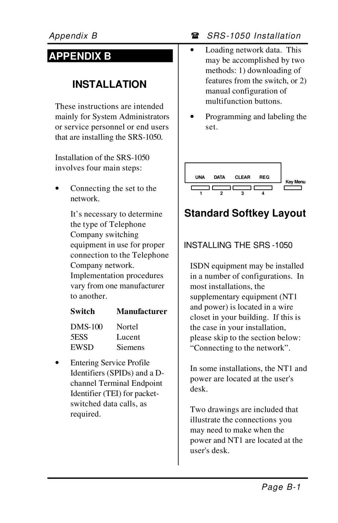
UNA DATA CLEAR REG
Key Menu
1 2 3 4
Standard Softkey Layout
INSTALLING THE SRS-1050
ISDN equipment may be installed in a number of configurations. In most installations, the supplementary equipment (NT1 and power) is located in a wire closet in your building. If this is the case in your installation, please skip to the section below: “Connecting to the network”.
In some installations, the NT1 and power are located at the user's desk.
Two drawings are included that illustrate the connections you may need to make when the power and NT1 are located at the user's desk.
Page