4.3.3.Connecting VLAN Groups
The switch supports communication within a common VLAN using
Traditional routers use only physical port numbers in their routing tables, which provides no support for VLANs. By contrast, this device supports Layer 3 routing by using both logical and physical port numbers to support VLANs and Layer 3 switching simultaneously.
By using the abstraction of a logical port number to represent a collection of physical switch ports in the same VLAN, Layer 3 switching can occur from one VLAN to another transparently, without changing the routing protocol and IP routing software, while Layer 2 switching is still used for
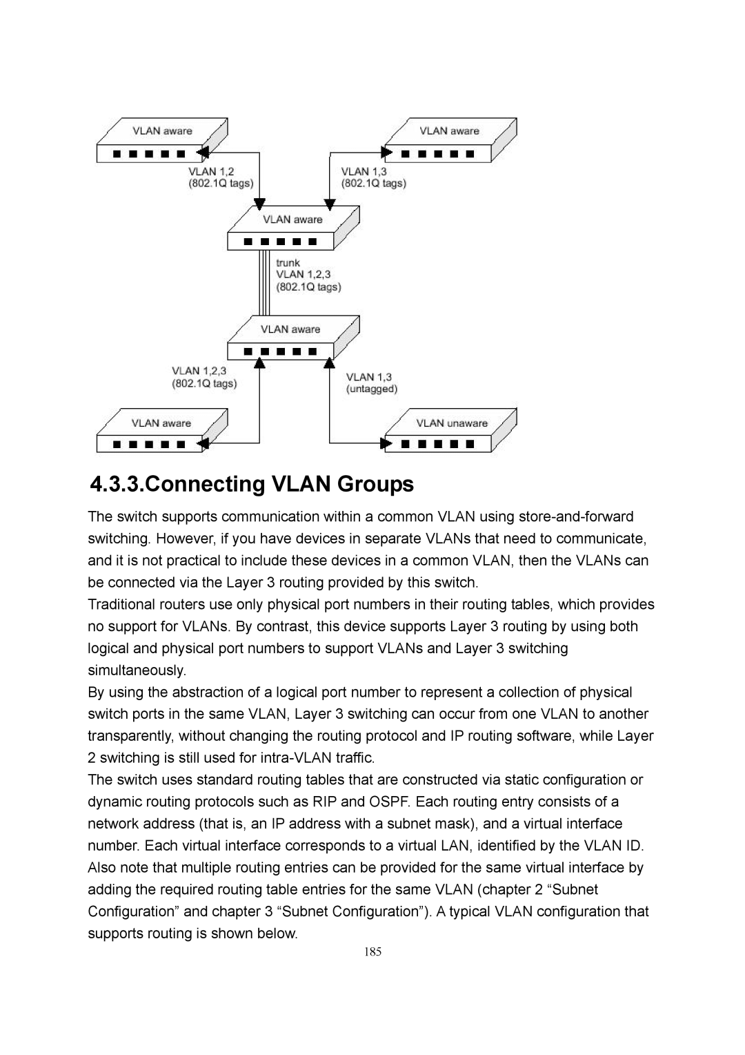
The switch uses standard routing tables that are constructed via static configuration or dynamic routing protocols such as RIP and OSPF. Each routing entry consists of a network address (that is, an IP address with a subnet mask), and a virtual interface number. Each virtual interface corresponds to a virtual LAN, identified by the VLAN ID. Also note that multiple routing entries can be provided for the same virtual interface by adding the required routing table entries for the same VLAN (chapter 2 “Subnet Configuration” and chapter 3 “Subnet Configuration”). A typical VLAN configuration that supports routing is shown below.
185