Table 5-1. PCI Slot Allocation in the Core Module
Slot Number | Board/Card Type | Comments |
PCI01 | Basic I/O Board | DVD: Connected by IDE interface |
|
| Incapable of Hot Plug. |
|
|
|
PCI02* | SCSI Card | DAT: Connected by SCSI interface. |
|
|
|
PCI03* | VGA Card | Display connected. |
|
| Incapable of Hot Plug. |
|
|
|
PCI04* | Free Slot |
|
|
|
|
PCI05* | Free Slot |
|
|
|
|
PCI06 | Free Slot |
|
|
|
|
PCI07 | Free Slot |
|
|
|
|
PCI08 | Free Slot |
|
|
|
|
PCI09 | LAN Card |
|
|
|
|
PCI10 | Free Slot | Second SCSI interface |
|
|
|
PCI11 | Free Slot | Device Bay V: connected by SCSI interface. |
*No long cards can be installed in these slots; fan modules occupy
|
|
|
|
|
|
|
|
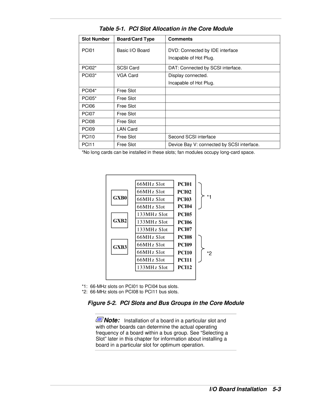
| 66MHz Slot | PCI01 |
|
|
|
| 66MHz Slot | PCI02 | *1 |
| GXB0 |
| |||
|
| 66MHz Slot | PCI03 | ||
|
|
| 66MHz Slot | PCI04 |
|
|
|
|
| ||
|
|
| 133MHz Slot | PCI05 |
|
| GXB2 |
|
| ||
|
| 133MHz Slot | PCI06 |
| |
|
|
| 133MHz Slot | PCI07 |
|
|
|
|
| ||
|
|
| 66MHz Slot | PCI08 |
|
| GXB3 |
| 66MHz Slot | PCI09 |
|
|
| 66MHz Slot | PCI10 | *2 | |
|
|
| |||
|
|
| |||
|
|
| 66MHz Slot | PCI11 |
|
|
|
| 133MHz Slot | PCI12 |
|
|
|
|
|
|
|
*1:
*2:
Figure 5-2. PCI Slots and Bus Groups in the Core Module
![]() Note: Installation of a board in a particular slot and with other boards can determine the actual operating frequency of a board within a bus group. See “Selecting a Slot” later in this chapter for information about installing a board in a particular slot for optimum operation.
Note: Installation of a board in a particular slot and with other boards can determine the actual operating frequency of a board within a bus group. See “Selecting a Slot” later in this chapter for information about installing a board in a particular slot for optimum operation.