DIMM Installation
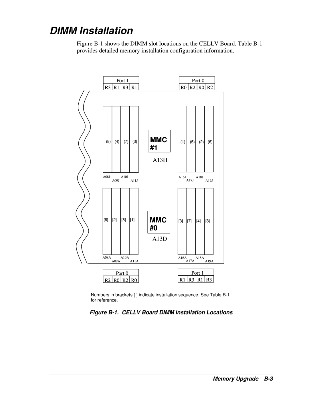
Figure B-1 shows the DIMM slot locations on the CELLV Board. Table B-1 provides detailed memory installation configuration information.
Port 1
R3 ![]() R1
R1 ![]() R3
R3 ![]() R1
R1
Port 0
R0 ![]() R2
R2 ![]() R0
R0 ![]() R2
R2
(8) (4) (7) (3)
MMC #1
A13H
(1)
(5) (2) (6)
A08J A09J A10J A11J | A16JA17J A18J A19J |
[6]
[2]
[5][1]
MMC #0
A13D
[3][7]
[4][8]
A08A A09AA10A A11A | A16AA17A A18A A19A |
Port 0
R2 ![]() R0
R0 ![]() R2
R2 ![]() R0
R0
Port 1
R1 ![]() R3
R3 ![]() R1
R1 ![]() R3
R3
Numbers in brackets [ ] indicate installation sequence. See Table