| Table |
|
|
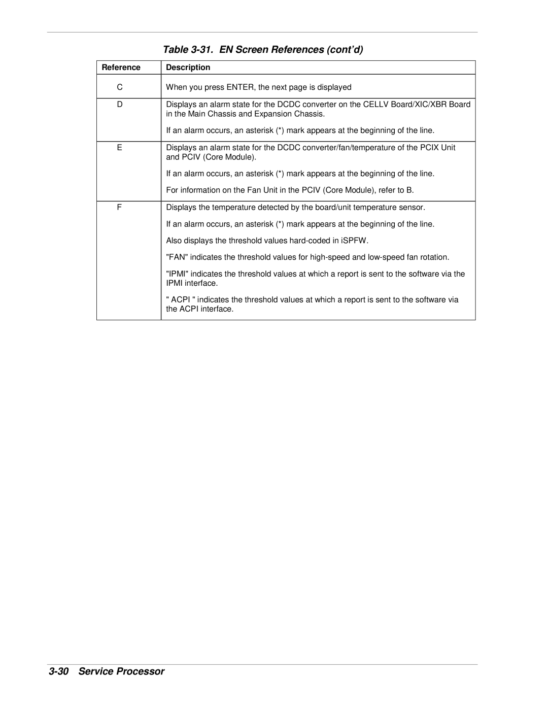
Reference | Description |
C | When you press ENTER, the next page is displayed |
|
|
D | Displays an alarm state for the DCDC converter on the CELLV Board/XIC/XBR Board |
| in the Main Chassis and Expansion Chassis. |
| If an alarm occurs, an asterisk (*) mark appears at the beginning of the line. |
|
|
E | Displays an alarm state for the DCDC converter/fan/temperature of the PCIX Unit |
| and PCIV (Core Module). |
| If an alarm occurs, an asterisk (*) mark appears at the beginning of the line. |
| For information on the Fan Unit in the PCIV (Core Module), refer to B. |
|
|
F | Displays the temperature detected by the board/unit temperature sensor. |
| If an alarm occurs, an asterisk (*) mark appears at the beginning of the line. |
| Also displays the threshold values |
| "FAN" indicates the threshold values for |
| "IPMI" indicates the threshold values at which a report is sent to the software via the |
| IPMI interface. |
| " ACPI " indicates the threshold values at which a report is sent to the software via |
| the ACPI interface. |
|
|