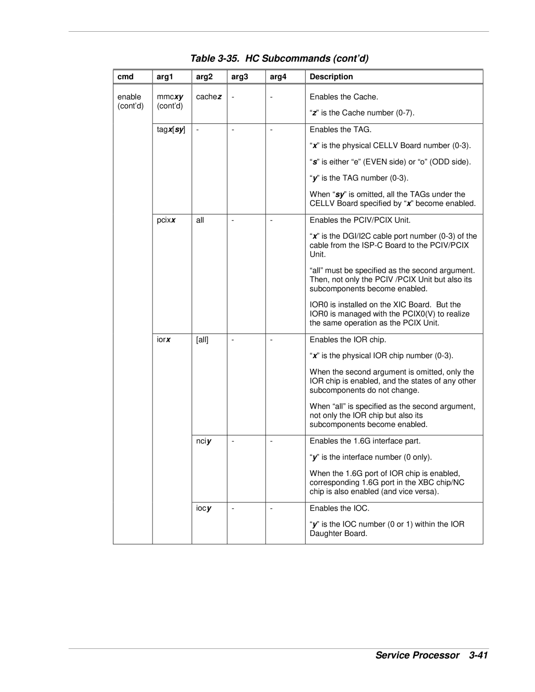
Table 3-35. HC Subcommands (cont’d)
cmd
arg1
arg2
arg3
arg4
Description
enable | mmcxy | cachez | - | - | Enables the Cache. |
(cont’d) | (cont’d) |
|
|
| “z” is the Cache number |
|
|
|
|
| |
|
|
|
|
|
|
| tagx[sy] | - | - | - | Enables the TAG. |
|
|
|
|
| “x” is the physical CELLV Board number |
|
|
|
|
| “s” is either “e” (EVEN side) or “o” (ODD side). |
|
|
|
|
| “y” is the TAG number |
|
|
|
|
| When “sy” is omitted, all the TAGs under the |
|
|
|
|
| CELLV Board specified by “x” become enabled. |
|
|
|
|
|
|
| pcixx | all | - | - | Enables the PCIV/PCIX Unit. |
|
|
|
|
| “x” is the DGI/I2C cable port number |
|
|
|
|
| cable from the |
|
|
|
|
| Unit. |
|
|
|
|
| “all” must be specified as the second argument. |
|
|
|
|
| Then, not only the PCIV /PCIX Unit but also its |
|
|
|
|
| subcomponents become enabled. |
|
|
|
|
| IOR0 is installed on the XIC Board. But the |
|
|
|
|
| IOR0 is managed with the PCIX0(V) to realize |
|
|
|
|
| the same operation as the PCIX Unit. |
|
|
|
|
|
|
| iorx | [all] | - | - | Enables the IOR chip. |
|
|
|
|
| “x” is the physical IOR chip number |
|
|
|
|
| When the second argument is omitted, only the |
|
|
|
|
| IOR chip is enabled, and the states of any other |
|
|
|
|
| subcomponents do not change. |
|
|
|
|
| When “all” is specified as the second argument, |
|
|
|
|
| not only the IOR chip but also its |
|
|
|
|
| subcomponents become enabled. |
|
|
|
|
|
|
|
| nciy | - | - | Enables the 1.6G interface part. |
|
|
|
|
| “y” is the interface number (0 only). |
|
|
|
|
| When the 1.6G port of IOR chip is enabled, |
|
|
|
|
| corresponding 1.6G port in the XBC chip/NC |
|
|
|
|
| chip is also enabled (and vice versa). |
|
|
|
|
|
|
|
| iocy | - | - | Enables the IOC. |
|
|
|
|
| “y” is the IOC number (0 or 1) within the IOR |
|
|
|
|
| Daughter Board. |
|
|
|
|
|
|
Service Processor