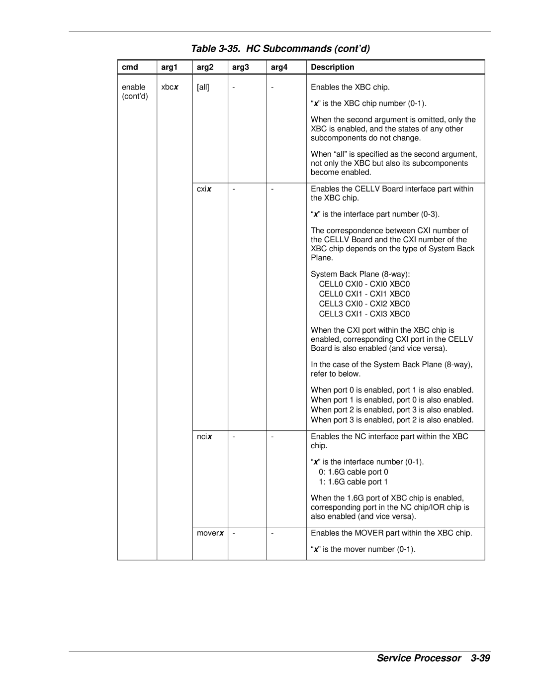
Table 3-35. HC Subcommands (cont’d)
cmd
arg1
arg2
arg3
arg4
Description
enable (cont’d)
xbcx
[all] | - | - | Enables the XBC chip. |
|
|
| “x” is the XBC chip number |
|
|
| When the second argument is omitted, only the |
|
|
| XBC is enabled, and the states of any other |
|
|
| subcomponents do not change. |
|
|
| When “all” is specified as the second argument, |
|
|
| not only the XBC but also its subcomponents |
|
|
| become enabled. |
|
|
|
|
cxix | - | - | Enables the CELLV Board interface part within |
|
|
| the XBC chip. |
|
|
| “x” is the interface part number |
|
|
| The correspondence between CXI number of |
|
|
| the CELLV Board and the CXI number of the |
|
|
| XBC chip depends on the type of System Back |
|
|
| Plane. |
|
|
| System Back Plane |
|
|
| CELL0 CXI0 - CXI0 XBC0 |
|
|
| CELL0 CXI1 - CXI1 XBC0 |
|
|
| CELL3 CXI0 - CXI2 XBC0 |
|
|
| CELL3 CXI1 - CXI3 XBC0 |
|
|
| When the CXI port within the XBC chip is |
|
|
| enabled, corresponding CXI port in the CELLV |
|
|
| Board is also enabled (and vice versa). |
|
|
| In the case of the System Back Plane |
|
|
| refer to below. |
|
|
| When port 0 is enabled, port 1 is also enabled. |
|
|
| When port 1 is enabled, port 0 is also enabled. |
|
|
| When port 2 is enabled, port 3 is also enabled. |
|
|
| When port 3 is enabled, port 2 is also enabled. |
|
|
|
|
ncix | - | - | Enables the NC interface part within the XBC |
|
|
| chip. |
|
|
| “x” is the interface number |
|
|
| 0: 1.6G cable port 0 |
|
|
| 1: 1.6G cable port 1 |
|
|
| When the 1.6G port of XBC chip is enabled, |
|
|
| corresponding port in the NC chip/IOR chip is |
|
|
| also enabled (and vice versa). |
|
|
|
|
moverx | - | - | Enables the MOVER part within the XBC chip. |
|
|
| “x” is the mover number |
|
|
|
|
Service Processor