Table 5-2. PCI Slot Allocation in the PCIX Unit
Configuration | Slot Number | Board/Card Type | Comments | |
Basic I/O Board, | PCI01 | Basic I/O Board* | DVD: Connected by IDE interface. | |
VGA Board, |
|
|
| |
PCI02 | SCSI Card | DAT: Connected by SCSI interface. | ||
SCSI Cards (for | ||||
DAT and Device |
|
|
| |
PCI03 | VGA Card* |
| ||
Bay), LAN Card |
|
|
| |
PCI04 | LAN Card |
| ||
|
| |||
|
|
|
| |
| PCI05 ~ PCI13 | Free Slots |
| |
|
|
|
| |
| PCI14 | SCSI Card | Device Bay V: Connected by SCSI | |
|
|
| interface | |
|
|
|
| |
SCSI Cards (for | PCI01 | SCSI Card | DAT: Connected by SCSI interface. | |
DAT and Device |
|
|
| |
PCI02 ~ PCI13 | Free Slots |
| ||
Bay) |
| |||
| PCI14 | SCSI Card | Device Bay: Connected by SCSI | |
|
|
| interface | |
|
|
|
| |
SCSI Card (for | PCI01 ~ PCI13 | Free Slots |
| |
Device Bay) |
|
|
| |
PCI14 | SCSI Card | Device Bay: Connected by SCSI | ||
| ||||
|
|
| interface | |
|
|
|
|
*Configuration for Core PCIX Unit.
66MHz Slot01
66MHz Slot02
66MHz Slot03
66MHz Slot04
133MHz Slot05
133MHz Slot06
133MHz Slot07
66MHz Slot08
66MHz Slot09
66MHz Slot10
66MHz Slot11
133MHz Slot12
133MHz Slot13
133MHz Slot14
*1
*2
*1:
*2:
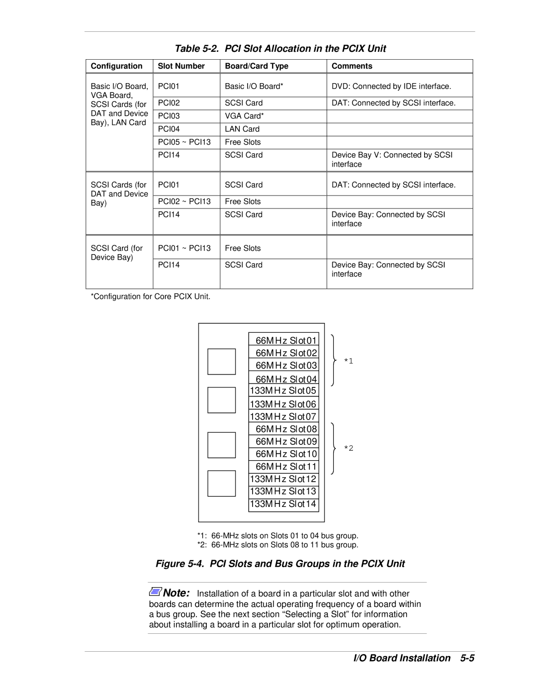
Figure 5-4. PCI Slots and Bus Groups in the PCIX Unit
![]() Note: Installation of a board in a particular slot and with other boards can determine the actual operating frequency of a board within a bus group. See the next section “Selecting a Slot” for information about installing a board in a particular slot for optimum operation.
Note: Installation of a board in a particular slot and with other boards can determine the actual operating frequency of a board within a bus group. See the next section “Selecting a Slot” for information about installing a board in a particular slot for optimum operation.
