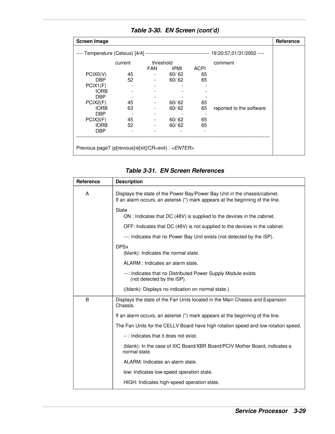
| Table | EN Screen (cont’d) | ||||
|
|
|
|
|
|
|
Screen Image |
|
|
|
|
| Reference |
| 19:20:57,01/31/2002 |
| ||||
| current | threshold |
| comment |
| |
|
| FAN | IPMI | ACPI |
|
|
PCIX0(V) | 45 | - | 60/ 62 | 65 |
|
|
DBP | 52 | - | 60/ 62 | 65 |
|
|
PCIX1(F) | - | - | - | - |
|
|
IORB | - | - | - | - |
|
|
DBP | - | - | - | - |
|
|
PCIX2(F) | 45 | - | 60/ 62 | 65 |
|
|
IORB | 63 | - | 60/ 62 | 65 | reported to the software |
|
DBP | - | - | - | - |
|
|
PCIX3(F) | 45 | - | 60/ 62 | 65 |
|
|
IORB | 52 | - | 60/ 62 | 65 |
|
|
DBP | - | - | - | - |
|
|
| ||||||
Previous page? (p[revious]/e[xit]/CR=exit) : <ENTER> |
|
|
| |||
|
|
|
|
|
|
|
|
| Table | |
|
|
|
|
| Reference | Description |
|
|
|
|
|
| A | Displays the state of the Power Bay/Power Bay Unit in the chassis/cabinet. |
|
|
| If an alarm occurs, an asterisk (*) mark appears at the beginning of the line. |
|
|
| State |
|
|
| ON : Indicates that DC (48V) is supplied to the devices in the cabinet. |
|
|
| OFF: Indicates that DC (48V) is not supplied to the devices in the cabinet. |
|
|
|
| |
|
| DPSx |
|
|
| (blank): Indicates the normal state. |
|
|
| ALARM : Indicates an alarm state. |
|
|
|
| |
|
| (not detected by the iSP). |
|
|
| ((blank): Displays no indication on normal state.) |
|
|
|
|
|
| B | Displays the state of the Fan Units located in the Main Chassis and Expansion |
|
|
| Chassis. |
|
|
| If an alarm occurs, an asterisk (*) mark appears at the beginning of the line. |
|
|
| The Fan Units for the CELLV Board have high rotation speed and low rotation speed. |
|
|
|
| |
|
| (blank): In the case of XIC Board/XBR Board/PCIV Mother Board, indicates a |
|
|
| normal state. |
|
|
| ALARM: Indicates an alarm state. |
|
|
| low: Indicates |
|
|
| HIGH: Indicates |
|
|
|
|
|
|
|
|
|
|
| Service Processor | |
