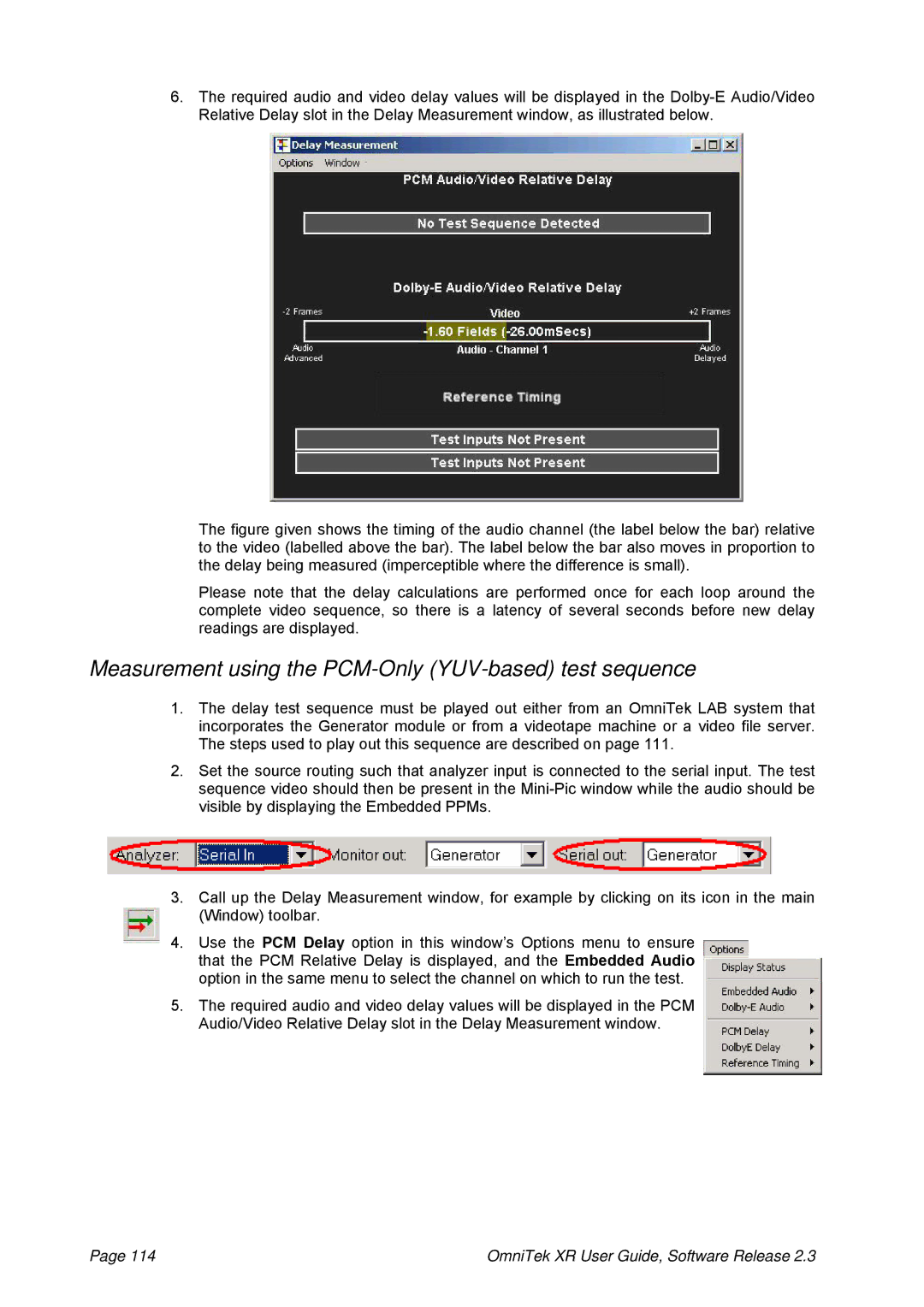
6.The required audio and video delay values will be displayed in the
The figure given shows the timing of the audio channel (the label below the bar) relative to the video (labelled above the bar). The label below the bar also moves in proportion to the delay being measured (imperceptible where the difference is small).
Please note that the delay calculations are performed once for each loop around the complete video sequence, so there is a latency of several seconds before new delay readings are displayed.
Measurement using the PCM-Only (YUV-based) test sequence
1.The delay test sequence must be played out either from an OmniTek LAB system that incorporates the Generator module or from a videotape machine or a video file server. The steps used to play out this sequence are described on page 111.
2.Set the source routing such that analyzer input is connected to the serial input. The test sequence video should then be present in the
3.Call up the Delay Measurement window, for example by clicking on its icon in the main (Window) toolbar.
4.Use the PCM Delay option in this window’s Options menu to ensure that the PCM Relative Delay is displayed, and the Embedded Audio option in the same menu to select the channel on which to run the test.
5.The required audio and video delay values will be displayed in the PCM Audio/Video Relative Delay slot in the Delay Measurement window.
Page 114 | OmniTek XR User Guide, Software Release 2.3 |