Data View Window
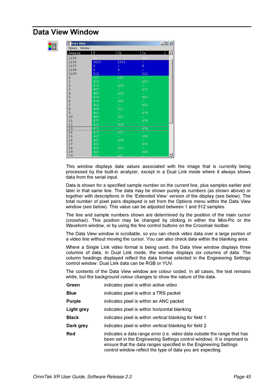
This window displays data values associated with the image that is currently being processed by the
Data is shown for a specified sample number on the current line, plus samples earlier and later in that same line. The data may be shown purely as numbers (as shown above) or together with descriptions in the ‘Extended View’ version of the display (see below). The total number of pixel pairs displayed is set from the Options menu within the Data View window (see below). This value can be adjusted between 1 and 512 samples.
The line and sample numbers shown are determined by the position of the main cursor (crosshair). This position may be changed by clicking in either the
The Data View window is scrollable, so you can check video data over a large portion of a video line without moving the cursor. You can also check data within the blanking area.
Where a Single Link video format is being used, the Data View window displays three columns of data. In Dual Link mode, the window displays six columns of data. The column headings displayed reflect the data format selected in the Engineering Settings control window. Dual Link data can be RGB or YUV.
The contents of the Data View window are colour coded. In all cases, the text remains white, but the background colour changes to show the nature of the data.
Green | indicates pixel is within active video |
Blue | indicates pixel is within a TRS packet |
Purple | indicates pixel is within an ANC packet |
Light grey | indicates pixel is within horizontal blanking |
Black | indicates pixel is within vertical blanking for field 1 |
Dark grey | indicates pixel is within vertical blanking for field 2 |
Red | indicates a data range error (i.e. video data outside the range that has |
| been set in the Engineering Settings control window). It is important to |
| ensure that the data ranges specified in the Engineering Settings |
| control window reflect the type of data you are expecting. |
OmniTek XR User Guide, Software Release 2.3 | Page 45 |