Audio Source and Metering type
Group and
Pair labels
Permitted Maximum reference level
Alignment reference level
Peak Hold markers
Highlighting indicating selection as pair ![]() for playback/
for playback/
Lissajous figure/
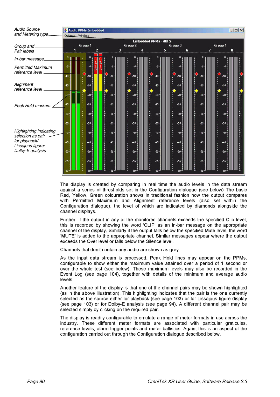
The display is created by comparing in real time the audio levels in the data stream against a series of thresholds set in the Configuration dialogue (see below) The basic Red, Yellow, Green colouration shows in traditional fashion how the output compares with Permitted Maximum and Alignment reference levels (also set within the Configuration dialogue), the level of which are indicated by diamonds alongside the channel displays.
Further, if the output in any of the monitored channels exceeds the specified Clip level, this is recorded by showing the word ‘CLIP’ as an
Channels that don’t contain any audio are shown as grey.
As the input data stream is processed, Peak Hold lines may appear on the PPMs, configurable to show either the maximum value attained over a period of 1 second or over the whole test (see below). These maximum levels may also be recorded in the Event Log (see page 104), together with details of the minimum and average audio levels.
Another feature of the display is that one of the channel pairs may be shown highlighted (as in the above illustration). This highlighting indicates that the pair is the one currently selected as the source either for playback (see page 103) or for Lissajous figure display (see page 103) or for
The display is readily configurable to emulate a range of meter formats in use across the industry. These different meter formats are associated with particular graticules, reference levels, alarm trigger points and meter ballistics. Again, this is an aspect of the configuration carried out through the Configuration dialogue described below.
Page 90 | OmniTek XR User Guide, Software Release 2.3 |