Software Release and ACD
Software Release Software Release
Programming Manual
726+,%$
FCC Requirements
Strata DK General End User Information
Radio Frequency Interference
Important Notice — Music-On-Hold
Introduction
Contents
Chapter 1 – Overview
Chapter 2 – Initialization & Test
Contents
Chapter 5 – Least Cost Routing
Chapter 4 – Toll Restriction
Chapter 7 – ISDN
Chapter 6 – Automatic Call Distribution
Chapter 8 – E911
Chapter 8 – E911
Contents
Strata DK Programming 5/99
Organization
Introduction
viii
Conventions
Enter
See Figure
Related Documents/Media
Related Documents/Media
Strata DK Installation & Maintenance Manual provides installation instructions for configuring and installing the Strata DK14, DK40i and DK424. It also includes T1/DS-1interface installation and configuration instructions, as well as fault finding flowcharts to troubleshoot the systems. An ACD Section provides instructions for installing ACD into the Strata DK424
Insight DK inView Quick Reference Guide provides instructions for viewing and customizing the on-screenwallboard and large character views of the real time call center data
Related Documents/Media
Introduction
Strata DK Programming 5/99
Numerical Program Listing
Overview
Numerical Program Listing
Overview
Strata DK Programming 5/99
Numerical Program Listing
Overview
Overview
Strata DK Programming 5/99
Numerical Program Listing
Overview
Toll Restriction Class Parameters
Strata DK Programming 5/99
Numerical Program Listing
Overview
Number of DID/DNIS Digits for Trunk Groups
Strata DK Programming 5/99
Numerical Program Listing
Overview
Assignments
Strata DK Programming 5/99
Feature or Topic
Alphabetical Program Listing
Feature or Topic
Overview
Alphabetical Program Listing
Overview
Strata DK Programming 5/99
DNIS
Alphabetical Program Listing
Overview
Strata DK Programming 5/99
Physical Port Display/Change
Programming Section Layout
How to Program a Strata DK System
1-10
see Figure
1-11
Program Sequence
To use the program sequence on the record sheet
Programming Data Variations
Multidimensional Programs
1-12
Simple Programs
Programming LED Buttons Keystrip Template
1-13
To check the status of a CO line in Program
Step 1: Check Minimum Hardware Requirements
First-timeProgramming
Step 2 Initialize the System
1-14
Step 4: Run Program
Step 3: Run Programs 03 and
Step 5: Set Date, Time and Day
Step 6: Run Additional Programs as Required
1-16
Programming Examples
Overview
Programming Examples
Initialization & Test
Program 91-9Overview
Program 91-9– System Initialization
Initialization & Test
Program 91-9Example
Action press buttons + LED Buttons
LCD Response
Program 90 Overview
Program 90 – Initialize Programs 00~*99
Initialization & Test
Program 90 Example
Action
LCD Response
CAUTION! Running Program 91-1drops all calls
Program 91-1Overview
Initialization & Test
Program 91-1Example
Action press buttons + LED Buttons
LCD Response
Programming Taking Effect
Program 91-2Overview
Program 92 Overview
Program 92 – Initializing Misc. Backup RAM
Program 92 – Initializing Misc. Backup RAM
Initialized Default: See individual programs
2-10
Program 92 Example
3. 6SNU6SHDNHU+ROG
4. 6SNU6SHDNHU
Program 92 – Initializing Misc. Backup RAM
2-11
Initialization & Test
Action press buttons + LED Buttons
2-12
Program 00 – Part 1: Software Check
6SNU+ROG6SNU+ROG6SNU+ROG6SNU+ROG
Initialized Default None
Program 00 Part 1 - Example
Program 00 Part 1 - Overview
2-13
Code 0, ROM Version
Initialization & Test
2-14
Action press buttons + LED Buttons
LCD Response
Program 00 – Part 2: Processor RAM Test
Backup RAM Test
General RAM Test
Display General RAM Test Results
Program 00 Part 2 - Overview
Display Backup RAM Test Results
2-16
TEST 2 X=OK Y=OK
Program 01 Overview
System & Station
6SNU
Program 02 Overview
Program 03 for DK14 – Slot Assignments
DK40i Base KSU
6SNU+ROG6SNU+ROG
DK40i Expansion KSU
System & Station
Program 03 for DK40i - Overview
DK424 Base Cabinet
6SNU+ROG6SNU+ROG6SNU+ROG
DK424 Expansion Cabinet
DK424 Expansion Cabinet
DK424 Expansion Cabinet
DK424 PCB Codes
DK424 Expansion Cabinet
DK424 Expansion Cabinet
Program 03 for DK424 - Overview
Manual to determine PCB slot placement
PIOU/PIOUS/RSSU
RWIU
RCIU/RCIS or RCIU2/RCIS
RCTU
RSIU
3-10
Program 03 Example
System & Station
6SNU6SHDNHU+ROG
3-11
Program *03 - Overview
Initialized Default: All cabinets =
System & Station
DK14 Record Sheet
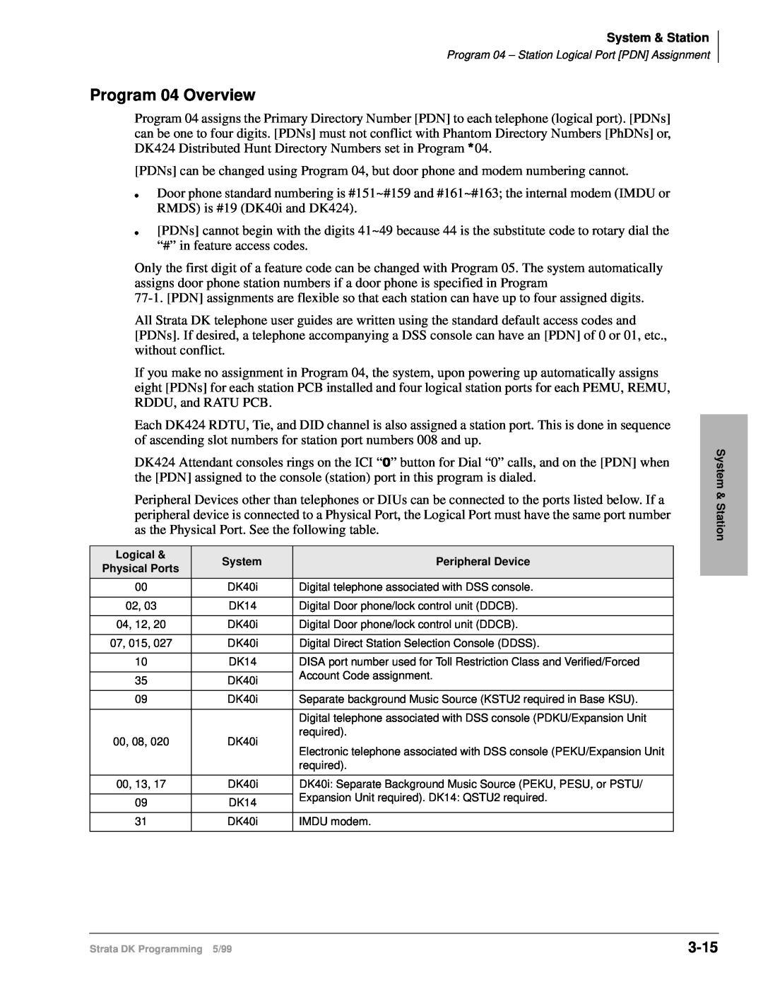
Program 04 – Station Logical Port PDN Assignment
DK40i Record Sheet
3-12
2.TBSU circuits configured for line-sideBRI
3-13
System & Station
Program 04 – Station Logical Port PDN Assignment
3-14
DK424 Record Sheet
6SNU+ROG6SNU+ROG6SNU+ROG6SNU+ROG
System & Station
3-15
Program 04 Overview
Logical &
System
3-16
Program 04 Example
System & Station
6SNU6SHDNHU+ROG
Initialized Default: See the legend below
3-17
6SNU+ROG6SNU+ROG6SNU+ROG6SNU+ROG
System & Station
3-18
Program *04 Overview
3-19
Program 05 – Flexible Access Code Numbering
Initialized Default See record sheet
Program 05 – Flexible Access Code Numbering
Program 05 – Flexible Access Code Numbering
3-20
Default PDNs and Park Orbits see Program
System & Station
3-21
Program 05 Overview
Program 05 Overview
3-22
only applies to Call Park Pickup
3-23
Program 09 Overview
Initialized Default Blank
6SNU+ROG6SNU+ROG6SNU+ROG6SNU+ROG
To assign a digit menu prompt to an ACD Group
3-24
6SNU
3-25
+ROG6SNU+ROG6SNU+ROG6SNU+ROG
Initialized Default: See legend below
3-26
Program *09 Overview
3-27
Program 10-1– System Assignments, Part 1 of
6SNU+ROG6SNU+ROG6SNU+ROG6SNU+ROG
System & Station
Program 10-1Overview
LED 17: Station-to-StationCall Volume PAD
3-28
LED 20: Two-COLine Conference
3-29
LED 04: Dual-tone Multi-frequencyDTMF Signal Time
LED 07: Ring Transfer of CO Line Allowed
LED 06: CO Line Repeat Ringing
3-30
Program 10-2– System Assignments, Part 2 of
6SNU+ROG6SNU+ROG6SNU+ROG6SNU+ROG
System & Station
3-31
Program 10-2Overview
LED 20: Padded Tone Return
LED 18: Two-COLine Conference
LED 15: External Page Included with All Call Page
3-32
LED 14: Privacy Override Warning Tone
LED 13: Auto Callback Camp-onTone
LED 08: Display Dialed Number Timing
3-33
LED 07: Standard Telephone Distinctive Ring
LED 05: Music-on-holdor Ring Back Tone
LED 01 Tone First/Voice First-DSSConsole
3-34
Program 10-3Overview
Program 10-3- System Assignments, Part 3 of
3-35
LED 20: SMDI Message Desk Number
LED 14: RS-232Voice Mail Signaling Method
LED 19: Speed Dial Entry Timeout
3-36
LEDs 13-10 SMDI Station Number Digit Length
3-37
LED 08: Caller ID / Automatic Number ID
LED 09: SMDI Bellcore Standard Version
3-38
Example
LEDs 01~04: Amplified Conference Assignments
3-39
Program *10 - Enhanced 911 Operation
Initialized Default See each program
Initialized Default: Blank
Programs *10-11and *10-12Overview
Program *10-92– E911 Pause Before Send Timer
Program *10-91– E911 Interdigital Time
3-40
Program 12 – System Assignments, Basic Timing
Code 1: Standard Telephone Ring Down Timer
Program 12 Overview
3-41
Code 3 Pause Timing
3-42
Code 4: Flashing Timing
Code 5: Pause After Flash
6SNU+ROG6SNU+ROG
Program 13 – Defining the Message Center
Program 13 Overview
3-43
6SNU+ROG6SNU+ROG6SNU+ROG
Program 15 - Ground/Loop/Tie/DID Line Options
3-44
Initialized Default: All LEDs are OFF
Program 15 Overview
Code 1: CO Outgoing Signal
3-45
Code 2: Line Pulse DP Rate
Code 4: Automatic Release AR Time
3-46
Code 5: Tandem Line Connection
Code 8: Operation After CO Line Flash
3-47
Program *15 – CO Line Tenant Assignments
Program 15 Overview
6SNU+ROG6SNU+ROG6SNU+ROG6SNU+ROG
6SNU+ROG6SNU
Program 16 – Assign CO Line Groups or Dial
3-48
System & Station
3-49
Program 16 Overview
Program 17 Overview
Program 17 - DID/Tie Line Options
3-50
LEDs 09, 10 and 14~20
LED 08 ANI/DNIS Digit Format
3-51
LED 07: ANI Receive Line Option
LED 06: Telephone LCD Display Option ANI or DNIS
LED 03: DID Camp-on/Busy
3-52
LED 02 Wink/Immediate
LED 01: Page/Handsfree Answerback
3-53
Program *17 Overview
Program Type: System Initialized Default: No data
6SNU+ROG6SNU+ROG6SNU+ROG6SNU+ROG
3-54
Program 19 Overview
PEKU/PESU
QSTU2, KSTU2, RSTU, RSTU2, RDSU, or PSTU
3-55
Program 20 Overview
Initialized Default: LED 17 ON, all others OFF
6SNU+ROG6SNU+ROG6SNU+ROG6SNU+ROG
3-56
Typical LED Settings for Program
LEDs 17~20: Data Security Groups
LEDs 12~16
3-57
LED 02: AT Commands and Result Codes
LED 06 DTR Pulse
LED 05: Auto Pause Behind PBX
3-58
Program 21 – Modem Pool Port Assignments
Program Type: Station Initialized Default: Blank
System & Station
3-59
Program 21 Overview
Program 22 Overview
+ROG6SNU+ROG
3-60
Initialized Default: No ports assigned
Initialized Default: No ports assigned
Note See Program 23 legend for port ranges
System & Station
Program 25-1Overview
Programs 23 and 24 Overview
3-62
3-63
Program 26 - Built-inAA Camp-onBusy Time
6SNU+ROG6SNU+ROG6SNU+ROG6SNU+ROG
System & Station
3-64
Program 26 Overview
3-65
Program 27 Overview
Program Type: Station Initialized Default: VR=2
Total DKT Volume Range VR
+ROG6SNU+ROG
3-66
System & Station
Processor Type: DK40i, All RCTUs
3-67
Program 28 Overview
3-68
The 1LJKW7UDQVIHUand $OO&DOO3DJHbuttons may
Code Table and Legend
6SNU+ROG6SNU+ROG6SNU+ROG
Program 29-1~8Overview
cause system operation problems
3-69
System & Station
3-70
Group
Group
6SNU +ROG6SNU
Program *29 – Add-onModules Button Assignments
Program *29 Overview
3-71
3-72
Button Assignments
3-73
Program 30 – Station Class of Service
Program 30 - Station Class of Service
System & Station
3-74
Program 30 Overview
LED 20: SLT/ISDN Terminal “#” Dial
LED 19: Privacy Override
LED 15 Change Verified Account Code
3-75
LED 14: Verified Account Code
3-76
LED 06 Automatic Busy Redial ABR Access
LED 10: Change DISA Security Code
LED 09: Change Toll Restriction TR Override Code
3-77
Program 30 - Example
LED 04: Call Pickup Code Option
LED 03: Microphone Button On at Start of Call
Program 30 – Station Class of Service
3-78
System & Station
+ROG
6SNU +ROG6SNU+ROG6SNU+ROG6SNU+ROG
Program *30 – Telephone Group Page Assignments
Program *30 Overview
3-79
Program 31 Overview
Program 31 – Station Class of Service
3-80
Program 31 – Station Class of Service
LED 09 – see above comments in Program Overview
3-81
3-82
LED 17: End-to-endSignal RCV VM
LED 20: Toshiba Stratagy/VP B + Station Number
LED 16: Receive Voice Mail VM ID Code
LED 13: OCA Handset Warning Tone
3-83
LED 11: Busy Override BOV Tone
LED 05~08: Voice Mail VM Groups 1~4
3-84
LED 04: Voice Mail VM to VM Call Blocking
LED 01: Handsfree Disabled
LED 03: Off-hookCall Announce OCA Enabled Receive
3-85
LED 02: Handsfree No Warning
6SNU +ROG6SNU+ROG6SNU+ROG6SNU+ROG
Program *31 – Group Pickup Assignments
Program *31 Overview
3-86
0= Disable Ringing Line Preference
3-87
1= Enable Ringing Line Preference
System & Station
3-88
Program 32 Overview
Program 32 – Automatic Preference
Program *32 Overview
6SNU +ROG6SNU+ROG6SNU+ROG6SNU+ROG
3-89
Program Type: Station Initialized Default: Blank
3-90
Program 33 Overview
Processor Type: DK14, DK40i, All RCTUs
3-91
Program 33 - Example
6SNU6SHDNHU+ROG
6SNU6SHDNHU
3-92
Program *33 – PhDN Owner Telephone Assignment
Initialized Default: Blanks no data
6SNU +ROG6SNU+ROG6SNU+ROG6SNU+ROG
3-93
Program *33 Overview
Program 34 Overview
Program 34 – Hold Recall Timing
3-94
6SNU+ROG6SNU+ROG6SNU+ROG6SNU+ROG
3-95
Program *34 – Station Class Of Service
Program *34 – Station Class Of Service
Initialized Default: LED 01 ON for all ports
3-96
Program *34 Overview
3-97
Program 35 - Station Class of Service
Program 35 - Station Class of Service
6SNU+ROG6SNU+ROG6SNU+ROG6SNU+ROG
3-98
Program 35 Overview
LED 18 Automatic Hold
LED 17: Continuous DTMF Tones Off
3-99
LEDs 13 and 14: Toll Restriction After Answer
LED 07~12
3-100
LED 06 Disable Hold Display Scrolling Release
LED 05: LCD Individual Message
LED 04: Message Waiting RCV
Program 36 Overview
Program 36 – Fixed Call Forward
3-101
5HGLDORU
31@
Program *36 Overview
3-102
Program 37 Overview
Program 37 – Ring Transfer Camp-onRecall Time
3-103
Program *37 Overview
Program *37 - Park Recall Timing
3-104
6SNU +ROG6SNU+ROG6SNU+ROG6SNU+ROG
Initialized Default: Assigns Code 31 to all ports
3-105
6SNU+ROG6SNU+ROG6SNU+ROG6SNU+ROG
System & Station
3-106
Program 38 Overview
3-107
Assignments for Electronic Telephone Keystrips
System & Station
or 0:/button is set appropriately in Program
System & Station
3-108
Strata DK Programming 5/99
16, 36, 56,
6SNU+ROG6SNU+ROG6SNU+ROG6SNU+ROG
3-109
System & Station
Program Type: Station
3-110
Program *38 Overview
3-111
Program 39 – Flexible Button Assignments
Initialized Default: See Program
6SNU+ROG6SNU+ROG6SNU+ROG6SNU+ROG
Program 39 Overview
Feature Buttons Assignments
3-112
To assign features to flexible buttons
System & Station
3-113
Program 39 – Flexible Button Assignments
Table
100~
3-114
3-115
Directory Number Button Assignments
To assign directory numbers to flexible buttons
System & Station
3-116
Program 39 – Flexible Button Assignments
Button Type
Set Call Forward for PhDNs
3-117
Strata AirLink does not support this feature
Alert Signal Button Assignments
3-118
System & Station
3-119
Alert Signal Button Programming Example
System & Station
Program 39 – Flexible Button Assignments
+ROG6SNU+ROG6SNU+ROG
6SNU +ROG6SNU
3-120
System & Station
3-121
Program *40 Overview
Series Overview
Program *41 for DK424 – T1 Assignment Series Part
3-122
Program *41-1Overview
3-123
Program *41-2 – T1 Channel Assignments
6SNU +ROG6SNU+ROG7XUQ6\VWHP3RZHU2VHFWKHQ
Initialized Default: 1 = Loop Start
Program *41-2Overview
3-124
Program *41-3Overview
Initialized Default 5 -6dB
3-125
Program *42 for DK424 - T1 Assignment Series Part
See “Program *42 – Clock Source”on Page
Initialized Default 4 -3dB
6SNU +ROG6SNU+ROG6SNU+ROG6SNU+ROG
3-126
Processor Type: DK14, DK40i, All RCTUs
3-127
Program *50 Overview
3-128
Program *51 – Station Memory Allocation
Initialized Default: No memory for all ports
6SNU +ROG6SNU+ROG6SNU+ROG6SNU+ROG
3-129
Program *51 Overview
Initialized Default: No station owners assigned
3-130
6SNU +ROG6SNU+ROG6SNU+ROG6SNU+ROG
System & Station
3-131
Program *52 Overview
Program 58 – DK424 Attendant Console Series Part
Program 58-1 – Attendant Console Overflow Timer
Program 58-2 – Attendant Console Display Type
6SNU+ROG6SNU+ROG6SNU+ROG6SNU+ROG
3-133
Program 58-4 –
Program 58-2Overview
LED 01 Attendant Console Display Type
Program 58-5Overview
3-134
Console
3-135
Console
Console
3-136
Program 59 Overview
System & Station
System & Station
3-137
Table
See Program *15 for Tenant Group assignments
3-138
Program 60-1Overview
Program 60-1- SMDR Data Output Options
3-139
Initialized Default: LED 01 OFF
Initialized Default: Item 2: 10 seconds
3-140
6SNU+ROG6SNU+ROG6SNU+ROG6SNU+ROG
System & Station
3-141
Program 60-2-7Overview
Item 2: SMDR Threshold Time
Item 3 SMDR Output
Program 60-8Overview
3-142
Two CO line connection in Program 10-1and Program
3-143
Program 69 – Verified Account Codes
Program Type: System Initialized Default: Blank
6SNU+ROG6SNUááá+ROG6SNU+ROG6SNU+ROG
3-144
Program 69 Overview
Account Code Digit Length
Full and Partially Verified Account Codes
Initialized Default: 000 for all VACNs
3-145
6SNU+ROG6SNU+ROG6SNU+ROG6SNU+ROG
System & Station
3-146
Program 70 Overview
DNIS Addresses
Program 71 - DNIS
Program 71-0:DID / Tie / DNIS / ANI Lines
DNIS/ANI Routing Destinations
DNIS Record Sheet
Program 71-5:DNIS Number Name Display
3-148
6SNU+ROG6SNUááá+ROG6SNU+ROG6SNU+ROG
Program 71-1~71-3Overview
Program 71-0Overview
3-149
DNIS Number
3-150
Program 71-4Overview
3-151
Program 71-5Overview
3-152
6SNU+ROG6SNU.%XWWRQ+ROG6SNU+ROG
System & Station
Program Type: System
Second Telephone Group
First Telephone Group
Program *71, *72, *73 Overview
3-153
Assignments
Program 72 – DNIS Number Network Table
3-154
6SNU+ROG6SNUááá+ROG6SNU+ROG6SNU+ROG
3-155
Program 72 Overview
Program 74 Overview
Program 74 – System NT Button Lock Password
3-156
Program 76-1Overview
Program 76-1X-Y– DK14, DK40i, All RCTUs
3-157
3-158
Program 76-2Overview
Initialized Default All ports 2400 bps
System & Station
RSIU / RSIS / RMDS, PIOU/PIOUS / IMDU, PEPU
Program 77-1– Peripheral Options Door Phones
3-159
Initialized Default: All LEDs are OFF
3-160
Program 77-1Overview
LED 20: Door Lock Time
LED 15: RMDS Protocol
3-161
LED 10: DKAdmin/Backup
LED 14 RMDS or IMDU Modem
LED 08: Door Phone Ring On External Page
LED 06: NT Relay
3-162
LED 05: MOH/NT Relay DK40i, DK424
Initialized Default: All LEDs are OFF
3-163
6SNU+ROG6SNU+ROG6SNU+ROG6SNU+ROG
System & Station
3-164
Program 77-2Overview
LED 20: Door Phone Ring Count
LEDs 04, 08, 12, and 16: Door Lock Assignments
3-165
Program 77-3Overview
Initialized Default Zones 1~4 assigned to tenant
6SNU+ROG6SNU+ROG6SNU+ROG6SNU+ROG
3-166
Program 77-4Overview
LED ON
LED OFF
3-167
3-168
Program 78 – CO Line Special Ringing Assignments
Initialized Default: All LEDs are OFF
6SNU+ROG6SNU+ROG6SNU+ROG
Feature 5: Ring IMDU or RMDS Maintenance Modem
Feature 2: DISA CO Line Assignment
Program 78 Overview
3-169
3-170
Program 79 – Door Phone Ringing
Initialized Default: All LEDs are OFF
6SNU+ROG6SNU+ROG6SNU+ROG6SNU+ROG
3-171
Program 79 Overview
LEDs 01~12: Door Phone Ring
Program *79 Overview
6SNU +ROG
3-172
3-173
Program 80 Overview
3-174
Program *80 Overview
6SNU +ROG6SNU+ROG6SNU+ROG6SNU+ROG
6SNU+ROG6SNU
3-175
System & Station
Program Type: System
Auto Attendant
Program 81~89 Overview
Station Ringing Modes
3-176
3-177
Attendant Console DK424 only
Attendant Console Load Sharing
Auto Attendant Delay Ring
Auto Attendant Program Example
3-178
To program the example
6SNU +ROG6SNU
3-179
System & Station
Program Type System
3-180
Programs *81, *84 and *87 Overview
Program *81
Program *84
System & Station
3-181
Ground/Loop Start
CO Incoming Call Ringing Control
3-182
Program 93 Overview
Program 93 – CO Line Identification
3-183
Numeric Mode
3-184
Alpha Mode
System & Station
Program 97 Overview
Program 97 – Printing Program Data through SMDR
3-185
Initialized Default: Prints out customer database
System & Station
3-186
Program 97 – Printing Program Data through SMDR
Strata DK Programming 5/99
Toll Restriction
Toll Restriction Features
Toll Restriction Methods
Simple Toll Restriction
Station Priority Classes 1~8
Special Common Carrier Authorization
Office Code Exception Tables
Toll Restriction Override by System Speed Dial
Completing the Toll Restriction System Record
Completing the Toll Restriction System Record
Program 40 – Station CO Line Access
Program 40 – Station CO Line Access
6SNU+ROG6SNU+ROG6SNU+ROG6SNU+ROG
Toll Restriction
Program 40 Overview
6SNU+ROG6SNU+ROG6SNU+ROG6SNU+ROG
Program 41 – Station Outgoing Call Restriction
Toll Restriction
Program 41 – Station Outgoing Call Restriction
Automatic Busy Redial ABR overrides Program
Program 41 Overview
Toll Restriction
6SNU+ROG6SNU+ROG6SNU+ROG6SNU+ROG
Processor Type: DK14, DK40i, All RCTUs
Program Type: Toll estriction
Program 42-0Overview
+ROG6SNU+ROG
Program 42-1~8- PBX/Centrex Access Codes
Program 42-1~8Overview
4-10
4-11
Program 43 – 0 + Credit Card Dialing Option
Initialized Default: All LEDS OFF
6SNU+ROG6SNU+ROG6SNU+ROG6SNU+ROG
4-12
Program 43 Overview
4-13
Program 44-1~8Overview
4-14
Program 44-91~93Overview
Program 45-1Overview
Program 45-1– LCR/Toll Restriction Dial Plan
4-15
Plan
4-16
Plan
4-17
Post 1995 North American Numbering Plan NANP
Plans 4~6
Plan
Plan 7 - 10XXX+1+NXX+NXX/NXX
4-18
Plan
Plan
Program 45-2Overview
Program 45-2– Toll Restriction Disable
4-19
Program 45-2– Toll Restriction Disable
Program 45-3~6- Special Common Carrier Numbers
and Authorization Code Digit Length
6SNU+ROG6SNU
Program 45-3~6Overview
Items 3 and
4-21
Items 4 and
Program 45-8~9Overview
Program 45-8~9– Toll Restriction Override Code
4-22
+ROG
4-23
Program *45-1Overview
6SNU +ROG6SNU+ROG6SNU+ROG6SNU+ROG
SELECT =
+ROG6SNU+ROG6SNU+ROG
Program *45-2Overview
4-24
Example Centrex assume
Example 10-digitDialing
4-25
4-26
Program *45-3Overview
+ROG6SNU+ROG6SNU+ROG
Processor Type: DK14, DK40i, All RCTUs
Example
4-27
Example
Program *45-4Overview
Program *45-4– Special Code Dialing Sequence with
LCR Example
4-28
F-MDT
4-29
4-30
Program 46-2~4Overview
Processor Type: DK14, DK40i, All RCTUs
Program Type: Toll estriction
6SNU+ROG
4-31
6SNU+ROG6SNU+ROG
6SNU+ROG
4-32
Program 46-6~8Overview
4-33
Programs 46-10~80Overview
LED 01: 0 Restricted
LED 02: 01 Restricted
4-34
LED 03: 1+AC+555 and AC+555 Allowed
4-35
Programs 46-11~46-81Overview
Initialized Default: Leaves all LEDs OFF
Toll Restriction
Toll Restriction
4-36
Processor Type: DK14, DK40i, All RCTUs
Program Type: Toll estriction
4-37
Program 47 Overview
Initialized Default: 100 for all ports
4-38
6SNU+ROG6SNU+ROG6SNU+ROG6SNU+ROG
Toll Restriction
4-39
Program 48 Overview
Digit Restriction
Station Restriction
Toll Restriction
4-40
Strata DK Programming 5/99
Least Cost Routing
LCR Features
Parameters
Home Area Code
LCR Station Access Priority Assignments
Timeout after 0 Zero
LCR Conditions
Area Code and Office Code Exceptions
LCR CO Line Programming Reference Table
Program 50-1– LCR Parameters
LED 01 Enable System LCR
Program 50-1Overview
LED 02: Not used
Program 50-2– LCR Home Area Code
LED Button 04: Dial Tone After LCR Access
Program 50-2Overview
Programs 50-31~5 Overview
Programs 50-31~5 – LCR Special Codes
Processor Type: DK14, DK40i, All RCTUs
Program 50-4Overview
Program 50-5Overview
Program 50-5– LCR Local Call Plan Number
+ROG6SNU+ROG6SNU+ROG
Program 50- - LCR Dial 0 Zero Time-out
Program 50-6Overview
Overview for Programs 51~54
5-10
Program 51 – LCR Area Codes
6SNU+ROG6SNU+ROG6SNU+ROG6SNU+ROG
Least Cost Routing
HMIS Example
Program 51 Overview
5-11
Example
6SNU+ROG6SNU+ROG6SNU+ROG6SNU+ROG
5-12
Least Cost Routing
Program Type
5-13
Program 52 Overview
Example
Example
6SNU+ROG6SNU+ROG6SNU+ROG6SNU+ROG
5-14
Least Cost Routing
Program Type
Program 53 Overview
Installation Requiring Time Scheduling Feature
5-15
HMIS Example
Hotel Administration unrestricted
5-16
Least Cost Routing
Guest Room with restricted calling
Program 54 Overview
Program 54 – LCR Route Definition Tables
5-17
Initialized Default
Route Definition Number
5-18
CO Line Group assigned in Program
Modified Digits Table
Program 55 Series Overview
Program 55 – LCR Modified Digits Table
5-19
5-20
Program 55-0Overview
Initialized Default: All tables blank
Least Cost Routing
5-21
6SNU+ROG6SNU+ROG
6SNU+ROG6SNUááá+ROG
Least Cost Routing
5-22
Program 55-1and 2 Overview
5-23
Program 56 – LCR Station Group Assignments
6SNU+ROG6SNU+ROG6SNU+ROG6SNU+ROG
Least Cost Routing
5-24
Program 56 Overview
HMIS Example
Automatic Call Distribution
Initialized Default: n/a
Program 03 Overview
Automatic Call Distribution
1.Enter Program 09.“SELECT” appears on the LCD
Program 09 Overview
1.Enter Program 09. “SELECT” appears on the LCD
Initialized Default: See table below
Related Programs
Program *09 Overview
Automatic Call Distribution
Program 10-4Overview
Program 10-4– ACD/ISDN Parameters
LED 12: BRI ISDN Timer
LED 11: PRI ISDN Timer
LED 14: ISDN Start Button Access Code
LED 03: Supervisor Monitor Tone and Display
6SNU+ROG6SNU+ROG6SNU+ROG6SNU
Program 11 – ACD Timing Assignments
Initialized Default See table below
Code 1~9 ACD Group Number Music Timer 1~3
Code 3: After Call Work Timer
Code 2: Ring Agent Timer
Code 4: Ring-Back-ToneRBT Timer
Program 11 Overview
Code 6: Call Waiting Alarm Timer
Code 5: Music Timers 1, 2, and
Code 7: Call Waiting Alarm Timer
Code 8: Alarm Guard Timer
6-11
Code 9 Call Disconnect Timer
6-12
Program 14-0Overview
Program 39 for lines that are in the ACD Group
6-13
Program 14-1Overview
6-14
Program *14-1Overview
6SNU +ROG6SNU+ROG6SNU+ROG6SNU+ROG
Program 18 Overview
Program 18 – Agent Names for SMIS/MIS Assignments
6-15
Numeric Mode
6-16
Automatic Call Distribution
Alpha Entry Example
Program 14-2Overview
Program 14-2– ACD Supervisor Passwords
6-17
6-18
Program *14-2Overview
6SNU +ROG6SNU
+ROG6SNU+ROG6SNU+ROG
If the assignments for an ACD Group: Overflow Queue Timer Program 14-4,Overflow Queue Point Program 14-5,and/or After Shift Program 14-6destinations are programmed as Normal Ringing or AA, DID/Tie/DNIS/ANI lines will be routed to the destination DN assigned in this program. This is because DID/Tie/DNIS/ANI lines cannot be assigned to AA or Normal CO line ringing
6-19
6-20
Program 14-3Overview
Initialized Default: all blanks
Automatic Call Distribution
Code 1: Announcement Port One
6-21
Code 2: Announcement Port Two
Code4: ACD Queue Music Source Port
Automatic Call Distribution
6-22
Strata DK Programming 5/99
Code
Program 14-4Overview
Program 14-4– Queue Time Out Overflow Destination
6-23
If the overflow destination is to a Normal Ring assignment Programs 81~89 and *81, *84, and *87, Attendant Console or the built-inAA, calls will exit queue and overflow if the destination is idle or busy. This assignment is not necessary if the overflow queue timer is set to infinity infinity = 0000 in Program
6-24
6-25
Program 14-5Overview
Call Queue Overflow Point OP Guide
6-26
A1M1A2M2A3M3or OP0
A1~A3 = Announcement Device 1~3
Overflow Operation
6-27
Non-RepeatingQueue Announcement
Assign music in Program
6-28
6SNU
Program 14- – After Shift Service Destination
6SNU +ROG
6-29
6-30
Program 14-6Overview
6-31
Program 14-71Overview
Initialized Default Queue Size =
Automatic Call Distribution
Program 14-72Overview
Program 14-72– Queue Size for Alarm
6-32
+ROG6SNU+ROG
Program 14-73Overview
Program 14-73– Queue Size for Alarm
6-33
6SNU+ROG6SNU+ROG6SNU+ROG6SNU+ROG
DATA = 0: No Alarm
Program 14-8– Alarm Pattern Assignments
DATA = 1 Immediate Alarm
DATA = 2: Call Waiting Alarm 1 and
Program 14-9Overview
Program 14-9– Work Unit Assignments
6-35
6-36
Program 71 - DID/Tie/DNIS/ANI Lines
Program 35 - Station Class of Service
Program 15 – Ground/Loop/Tie/DID Line Options
$&3LFNXS
6-37
Automatic Call Distribution
Program 90, 91-1,or 91-9initializes Program
ACD Feature Button
6-38
Automatic Call Distribution
Program
Automatic Call Distribution
6-39
Call
Strata DK Programming 5/99
6-40
Related Programs
Program 39 Overview
Flowchart 6-1ACD Group Call Routing
6-41
Automatic Call Distribution
Automatic Call Distribution
Flowchart 6-2ACD Group Queue/Overflow Operation
6-42
Automatic Call Distribution
Strata DK Programming 5/99
Flowchart 6-3ACD Time Out Overflow
6-43
Automatic Call Distribution
Automatic Call Distribution
Flowchart 6-4ACD Overflow Point
6-44
Automatic Call Distribution
Strata DK Programming 5/99
Flowchart 6-5After Shift Operation
6-45
Automatic Call Distribution
Call Distribution
Automatic Call Distribution
6-46
Strata DK Programming 5/99
ACD Ca
Automatic Call Distribution
6-47
Automatic Call
Distribution
Start: call enters queue from ACD Flowchart
6-48
Automatic Call Distribution
Overflow after announcement/music or
Start: call enters queue from ACD Flowchart
6-49
Automatic Call Distribution
Call Distribution
the queue timer in Program 11-1expires
6-50
the disconnect timer in Program 11-9expires
Automatic Call Distribution
Start: call enters queue from ACD Flowchart
6-51
Automatic Call Distribution
Call Distribution
Automatic Call Distribution
6-52
Strata DK Programming 5/99
System Programs Overview
ISDN
ISDN
Flowchart
ISDN Related Programs
ISDN Related Programs
ISDN
Flowchart 7-2ISDN Trunk Programs
ISDN Related Programs
Standard Trunks
Primary Rate Interface PRI Programming
Trunk Programs Overview
ISDN
Program 16 – Assign CO Line Groups
Program 16 – Assign CO Line Groups
Strata DK Programming 5/99
Program *16 Overview
Program *16 – ISDN Trunk Group Type Assignment
Program *42 Series Overview
Program *42 – Clock Source
6SNU +ROG6SNU+ROG6SNU+ROG6SNU+ROG
Primary/Back-UpAssignments Example
Program *42-1Overview Release 3.1 and earlier
DK424 Master free run Assignment Example
Program *42-2Overview Release 3.1 and earlier
7-10
Program *43-1~3Overview
Program *43-1Overview
6SNU +ROG6SNU+ROG6SNU+ROG6SNU+ROG
7-11
Program *43-2Overview
Program *43-3Overview
Program *43-3– Network PRI Interface Assignment
7-12
Initialized Default: Blank see Important! below
7-13
Program *44 Overview
ISDN
BRI Trunk
7-14
Program *60 Overview
Program *61 Overview
Program *61 - Analog Trunk Services for ISDN
7-15
Initialized Default: see below
Program *62 Overview
Program *62 – Non-ISDNStation Bearer Service
7-16
Initialized Default: see below
Program *63 Overview
Program *63 – ISDN Dialing Parameters
7-17
6SNU+ROG
Program *64-1Overview
Program *64-1– Direct Inward Dialing Parameters
7-18
6SNU
7-19
Program *64-2Overview
+ROG
Program *65 Overview
Program *65 – ISDN Channel Group Assignment
7-20
6SNU +ROG6SNU+ROG6SNU+ROG6SNU+ROG
Program *66-1Overview
Program *66-1– Channel Group Number Parameters
7-21
6SNU +ROG6SNU
Program *66-2Overview
7-22
+ROG6SNU+ROG6SNU+ROG
7-23
Program *66-4 Call-by-CallNetwork ID
Program *66-4Overview
Record Sheet
Program *66-3Overview
Program *66-3- Channel Group/Trunk Parameters
7-24
Program *66-4 Call-by-CallNetwork ID
7-25
Program *66-5Overview
6SNU +ROG6SNU+ROG6SNU+ROG6SNU+ROG
7-26
Program *66-6Overview
For Programs *66-5and *66-6
6SNU +ROG6SNU+ROG6SNU+ROG6SNU+ROG
Program *66-7Overview
Program *66-7– LDN/Trunk Group Assignments
7-27
Initialized Default: Blank
Program *67-1Overview
Program *67-1– Trunk Group Call Direction
7-28
Initialized Default: Both Way
7-29
Program *67-2Overview
6SNU +ROG6SNU+ROG6SNU+ROG6SNU+ROG
7-30
Program *67-3Overview
Initialized Default: Default =
+ROG6SNU+ROG6SNU+ROG
7-31
Program *67-4Overview
6SNU +ROG6SNU+ROG6SNU+ROG6SNU+ROG
Program *67-5Overview
Program *67-5– Multiple Time Zone Settings
7-32
+ROG6SNU+ROG6SNU+ROG
7-33
Program *68-1Overview
LED 01: Outgoing Caller ID
LED 02: Outgoing Caller ID Status Change
Program *68-2Overview
Program *68-2– Outbound CNIS Parameters
7-34
6SNU+ROG6SNU+ROG
Program *69-1Overview
Program *69-1- CNIS Presentation Parameters
6SNU +ROG6SNU+ROG6SNU+ROG
7-35
Program *69-2Overview
Program *69-2- Special Number Assignment
6SNU +ROG6SNU+ROG6SNU+ROG6SNU+ROG
7-36
Operation Overview
E911
SMDR
Programming Overview
LED 10~07: CAMA Trunk Circuits Enabled/Disabled
LED 11: CAMA Operation Enabled/Disabled
Program *11-0– E911/CAMA Trunk Assignments
Program *11-0Overview
LED 02 CAMA Trunk Disconnect Operation Options
Program *11-1Overview
Program *11-1– CAMA Trunk Group Line Assignments
6SNU +ROG6SNU+ROG6SNU+ROG6SNU+ROG
6SNU +ROG6SNU+ROG6SNU+ROG6SNU+ROG
Program *11-2Overview
Program *11-5Overview
Program *11-5– CAMA Digits Sent on 911 Calls
6SNU +ROG6SNU+ROG6SNU+ROG6SNU+ROG
Program *11-6Overview
Program *11-6- E911 Interdigital Timer
8-10
Program *11-8Overview
Initialized Default: Data, Blank
6SNU +ROG6SNU+ROG6SNU+ROG6SNU+ROG
Program *12 Overview
Program *12 – CESID Station Information
6SNU +ROG6SNU;;+ROG6SNU+ROG6SNU+ROG
8-11
NYY = Office Code XXXX= Station Directory Number
8-12
8-13
Program *13 Overview
Processor Type: All RCTUs Release
E911
8-14
Strata DK Programming 5/99
GL-1
Glossary
CCVY CLASS CLID or CND CO CO Line CODECs DADM
GL-2
D-channel DDCB DDSS DIL DID Line DISA DK
DKAdmin DKBackup DKT DKT2000 series DKSU14A
GL-3
DKSUBI40 DN DNIS DPFT DSS DTMF DVSU
E911 EKT ESF EOCU FCC HDCB HDSS HESB HESC-65A
GL-4
HHEU HPFB HVSU2 IMDU ISDN
K4RCU3 KCDU KKYS KSTU2 LATA LCD LCR LDI LED LSI
GL-5
MDF MDFB MOH NDTU NT-1 OCA
Note Replaced by RPCI-DI
GL-6
OPS PBTC PBX PCB PCM PCOU PDIU-DI2 PDIU-DS PDKU2
PDN PEKU PEMU PEPU
PESU PhDN PIOU PIOUS
GL-7
PPTC PPTC PPTC-9 PPTC-25F PRI PSTU2 PSTN QCDU2
QKYS QSTU2 QRCU2 RAM RATU RBDB RBSU RBSS
GL-8
RBTC1A-2M RBUU RBUS RCMS
RMCU RCCB RCIU2/RCIS RCOS RCOU RCTU RDDU RDSU
GL-9
RDTU REMU RFIF RGLU
RKYS RMDS RPCI-DI RPTU ROM RPSB 1 and RPSU280
GL-10
RRCS RSIS
RSIU RSTU RSTU2 RWBF1 RWIU/WWIS RFMF R48S SDN SF
GL-11
SLT SMDI SMIS SSTU S/T Interface TAPI
See RDTU
GL-12
TA T1/DS-1 TCIU1 TCIU2 TCOU TDDU TE TSPI TSIU TTY
U Interface Universal slot WSIU
IN-1
Index
IN-2
3-11
IN-3
3-17
3-39
3-40
IN-4
6-18
3-47
2-15
IN-5
3-19
3-41
5-17
IN-6
5-19
IN-7
Index
IN-8
Strata DK Programming 5/99