4.18 System Board/RTC | 4 Replacement Procedures | ||
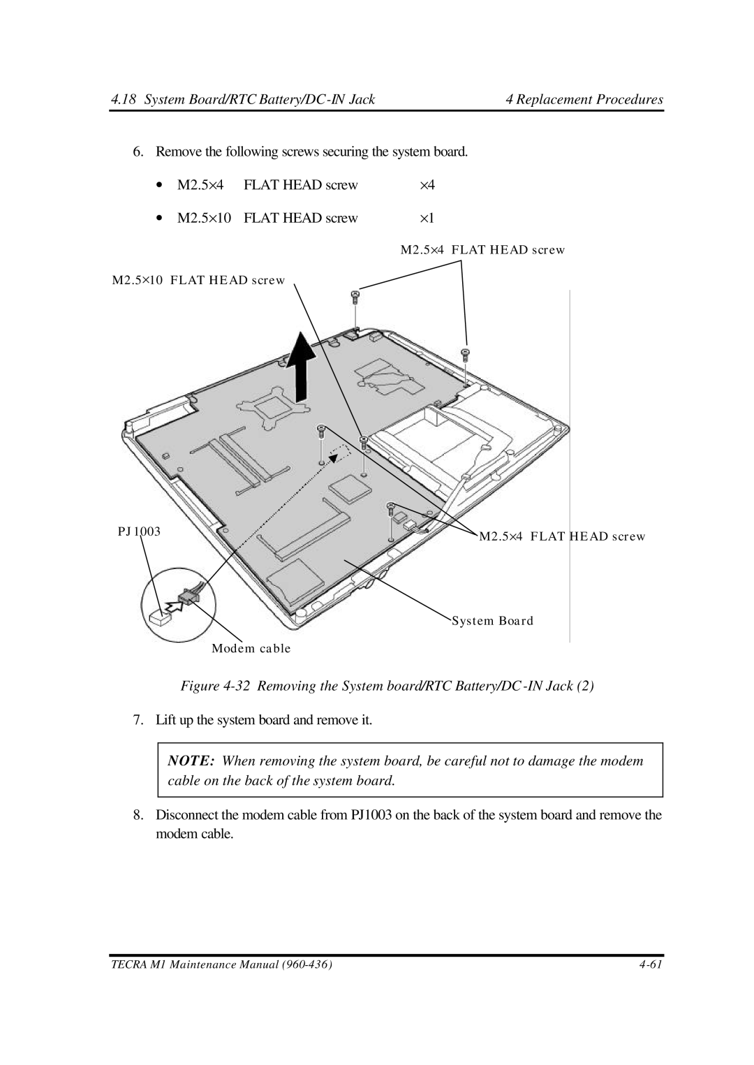
6. Remove the following screws securing the system board. | |||
∙ | M2.5×4 | FLAT HEAD screw | ×4 |
∙ | M2.5×10 | FLAT HEAD screw | ×1 |
M2.5×4 FLAT HEAD screw
M2.5×10 FLAT HEAD screw
PJ1003 | M2.5×4 FLAT HEAD screw | |
|
| |
|
| System Board |
|
| Modem cable |
|
| Figure |
7. Lift up the system board and remove it. | ||
|
|
|
|
| NOTE: When removing the system board, be careful not to damage the modem |
|
| cable on the back of the system board. |
|
|
|
8.Disconnect the modem cable from PJ1003 on the back of the system board and remove the modem cable.
TECRA M1 Maintenance Manual |