2 Troubleshooting Procedures | 2.5 FDD Troubleshooting |
Procedure 3 Connector Check and Replacement Check
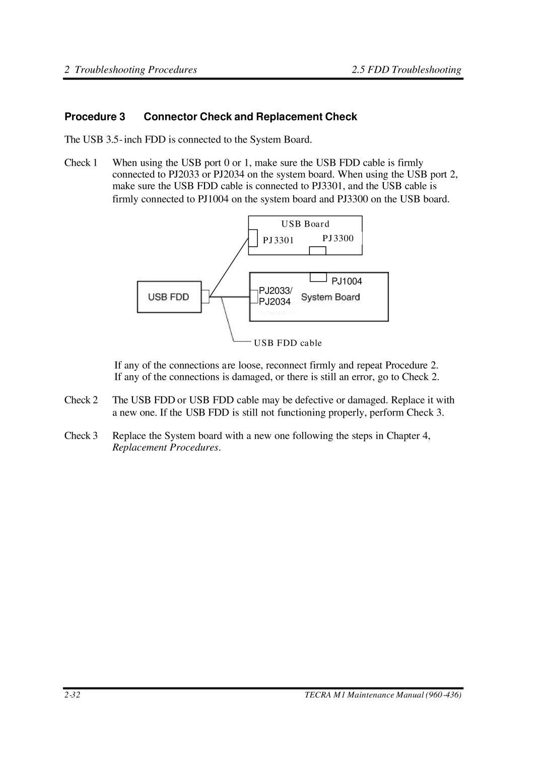
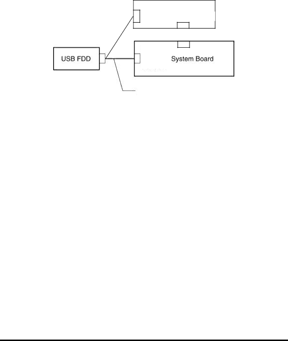
The USB 3.5- inch FDD is connected to the System Board.
Check 1 When using the USB port 0 or 1, make sure the USB FDD cable is firmly connected to PJ2033 or PJ2034 on the system board. When using the USB port 2, make sure the USB FDD cable is connected to PJ3301, and the USB cable is firmly connected to PJ1004 on the system board and PJ3300 on the USB board.
USB Board
PJ3301 PJ3300
PJ1004
PJ2033/
PJ2034
USB FDD cable
If any of the connections are loose, reconnect firmly and repeat Procedure 2. If any of the connections is damaged, or there is still an error, go to Check 2.
Check 2 The USB FDD or USB FDD cable may be defective or damaged. Replace it with a new one. If the USB FDD is still not functioning properly, perform Check 3.
Check 3 Replace the System board with a new one following the steps in Chapter 4, Replacement Procedures.
TECRA M1 Maintenance Manual (960 |