4.6 Slim Select Bay Module | 4 Replacement Procedures |
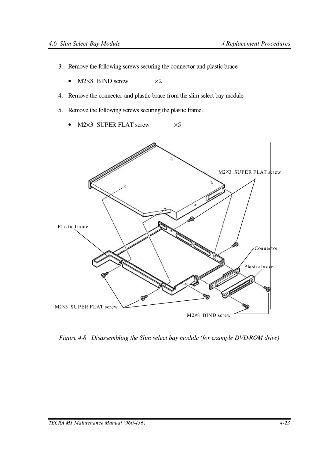
3. Remove the following screws securing the connector and plastic brace. | |
∙ M2×8 BIND screw | ×2 |
4.Remove the connector and plastic brace from the slim select bay module.
5.Remove the following screws securing the plastic frame.
∙ M2×3 SUPER FLAT screw | ×5 |
M2×3 SUPER FLAT screw
Plastic frame
Connector
Plastic brace
M2×3 SUPER FLAT screw
M2×8 BIND screw
Figure 4-8 Disassembling the Slim select bay module (for example DVD-ROM drive)
TECRA M1 Maintenance Manual |