4 Replacement Procedures | 4.7 Modem Daughter Card |
2. Remove the following screws securing the modem daughter card.
∙ M2×4 BIND screw | ×2 |
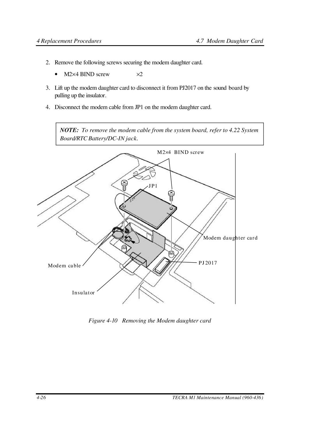
3.Lift up the modem daughter card to disconnect it from PJ2017 on the sound board by pulling up the insulator.
4.Disconnect the modem cable from JP1 on the modem daughter card.
NOTE: To remove the modem cable from the system board, refer to 4.22 System Board/RTC
M2×4 BIND screw
JP1
Modem daughter card
Modem cable | PJ2017 |
|
Insulator
Figure 4-10 Removing the Modem daughter card
TECRA M1 Maintenance Manual |