P R E L I M I N A R YAMD
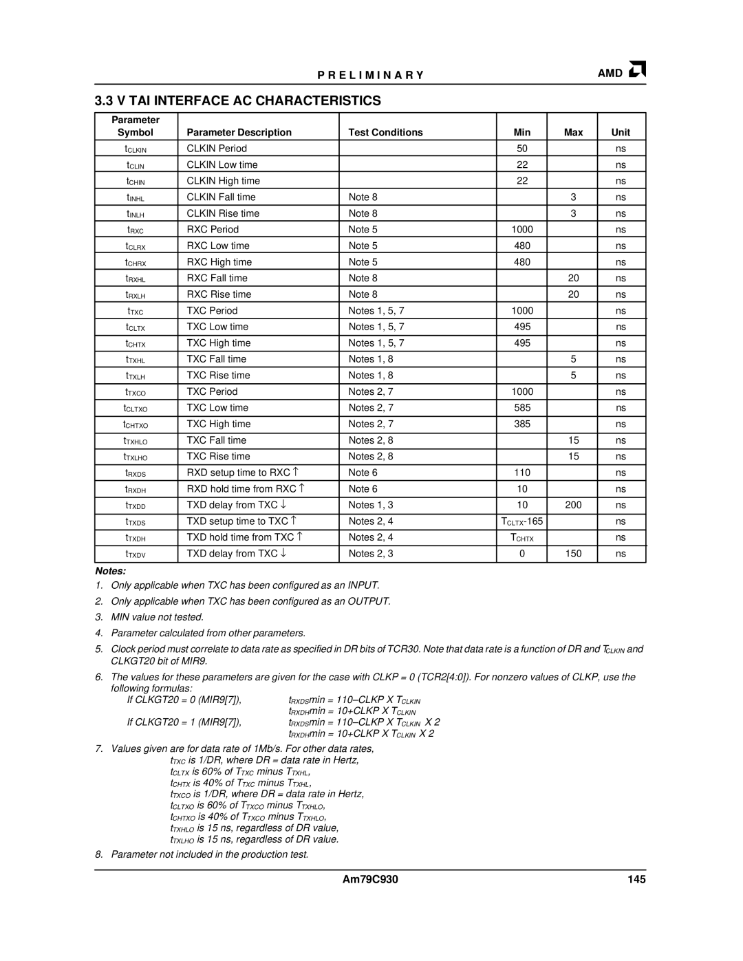
3.3 V TAI INTERFACE AC CHARACTERISTICS
Parameter |
|
|
|
|
|
Symbol | Parameter Description | Test Conditions | Min | Max | Unit |
|
|
|
|
|
|
tCLKIN | CLKIN Period |
| 50 |
| ns |
|
|
|
|
|
|
tCLIN | CLKIN Low time |
| 22 |
| ns |
tCHIN | CLKIN High time |
| 22 |
| ns |
tINHL | CLKIN Fall time | Note 8 |
| 3 | ns |
|
|
|
|
|
|
tINLH | CLKIN Rise time | Note 8 |
| 3 | ns |
|
|
|
|
|
|
tRXC | RXC Period | Note 5 | 1000 |
| ns |
tCLRX | RXC Low time | Note 5 | 480 |
| ns |
tCHRX | RXC High time | Note 5 | 480 |
| ns |
tRXHL | RXC Fall time | Note 8 |
| 20 | ns |
|
|
|
|
|
|
tRXLH | RXC Rise time | Note 8 |
| 20 | ns |
|
|
|
|
|
|
tTXC | TXC Period | Notes 1, 5, 7 | 1000 |
| ns |
|
|
|
|
|
|
tCLTX | TXC Low time | Notes 1, 5, 7 | 495 |
| ns |
|
|
|
|
|
|
tCHTX | TXC High time | Notes 1, 5, 7 | 495 |
| ns |
|
|
|
|
|
|
tTXHL | TXC Fall time | Notes 1, 8 |
| 5 | ns |
|
|
|
|
|
|
tTXLH | TXC Rise time | Notes 1, 8 |
| 5 | ns |
|
|
|
|
|
|
tTXCO | TXC Period | Notes 2, 7 | 1000 |
| ns |
|
|
|
|
|
|
tCLTXO | TXC Low time | Notes 2, 7 | 585 |
| ns |
|
|
|
|
|
|
tCHTXO | TXC High time | Notes 2, 7 | 385 |
| ns |
|
|
|
|
|
|
tTXHLO | TXC Fall time | Notes 2, 8 |
| 15 | ns |
|
|
|
|
|
|
tTXLHO | TXC Rise time | Notes 2, 8 |
| 15 | ns |
|
|
|
|
|
|
tRXDS | RXD setup time to RXC − | Note 6 | 110 |
| ns |
|
|
|
|
|
|
tRXDH | RXD hold time from RXC − | Note 6 | 10 |
| ns |
|
|
|
|
|
|
tTXDD | TXD delay from TXC ↓ | Notes 1, 3 | 10 | 200 | ns |
|
|
|
|
|
|
tTXDS | TXD setup time to TXC − | Notes 2, 4 |
| ns | |
|
|
|
|
|
|
tTXDH | TXD hold time from TXC − | Notes 2, 4 | TCHTX |
| ns |
|
|
|
|
|
|
tTXDV | TXD delay from TXC ↓ | Notes 2, 3 | 0 | 150 | ns |
|
|
|
|
|
|
Notes:
1.Only applicable when TXC has been configured as an INPUT.
2.Only applicable when TXC has been configured as an OUTPUT.
3.MIN value not tested.
4.Parameter calculated from other parameters.
5.Clock period must correlate to data rate as specified in DR bits of TCR30. Note that data rate is a function of DR and TCLKIN and CLKGT20 bit of MIR9.
6.The values for these parameters are given for the case with CLKP = 0 (TCR2[4:0]). For nonzero values of CLKP, use the following formulas:
If CLKGT20 = 0 (MIR9[7]),
If CLKGT20 = 1 (MIR9[7]),
7.Values given are for data rate of 1Mb/s. For other data rates, tTXC is 1/DR, where DR = data rate in Hertz, tCLTX is 60% of TTXC minus TTXHL,
tCHTX is 40% of TTXC minus TTXHL,
tTXCO is 1/DR, where DR = data rate in Hertz, tCLTXO is 60% of TTXCO minus TTXHLO,
tCHTXO is 40% of TTXCO minus TTXHLO,
tTXHLO is 15 ns, regardless of DR value, tTXLHO is 15 ns, regardless of DR value.
8.Parameter not included in the production test.
Am79C930 | 145 |