AMD | P R E L I M I N A R Y |
|
|
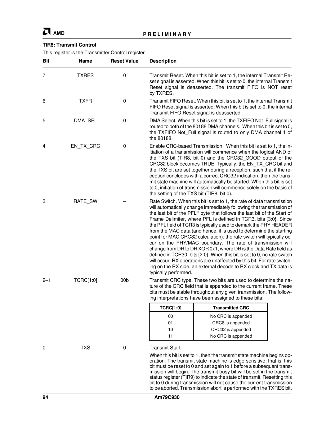
TIR8: Transmit Control
This register is the Transmitter Control register.
Bit | Name | Reset Value |
| Description |
|
|
|
|
|
|
|
|
|
|
|
7 | TXRES | 0 |
| Transmit Reset. When this bit is set to 1, the internal Transmit Re- | |||
|
|
|
| set signal is asserted. When this bit is set to 0, the internal Transmit | |||
|
|
|
| Reset signal is deasserted. The transmit FIFO is NOT reset | |||
|
|
|
| by TXRES. |
|
|
|
6 | TXFR | 0 |
| Transmit FIFO Reset. When this bit is set to 1, the internal Transmit | |||
|
|
|
| FIFO Reset signal is asserted. When this bit is set to 0, the internal | |||
|
|
|
| Transmit FIFO Reset signal is deasserted. | |||
5 | DMA_SEL | 0 |
| DMA Select. When this bit is set to 1, the TXFIFO Not_Full signal is | |||
|
|
|
| routed to both of the 80188 DMA channels. When this bit is set to 0, | |||
|
|
|
| the TXFIFO Not_Full signal is routed to only DMA channel 1 of | |||
|
|
|
| the 80188. |
|
|
|
4 | EN_TX_CRC | 0 |
| Enable | |||
|
|
|
| itiation of a transmission will commence when the logical AND of | |||
|
|
|
| the TXS bit (TIR8, bit 0) and the CRC32_GOOD output of the | |||
|
|
|
| CRC32 block becomes TRUE. Typically, the EN_TX_CRC bit and | |||
|
|
|
| the TXS bit are set together during a reception, such that if the re- | |||
|
|
|
| ception concludes with a correct CRC32 indication, then the trans- | |||
|
|
|
| mit state machine will automatically be started. When this bit is set | |||
|
|
|
| to 0, initiation of transmission will commence solely on the basis of | |||
|
|
|
| the setting of the TXS bit (TIR8, bit 0). | |||
3 | RATE_SW | – | Rate Switch. When this bit is set to 1, the rate of data transmission | ||||
|
|
|
| will automatically change immediately following the transmission of | |||
|
|
|
| the last bit of the PFLth byte that follows the last bit of the Start of | |||
|
|
|
| Frame Delimiter, where PFL is defined in TCR3, bits [3:0}. Since | |||
|
|
|
| the PFL field of TCR3 is typically used to demark the PHY HEADER | |||
|
|
|
| from the MAC data (and hence, it is used to determine the starting | |||
|
|
|
| point for MAC CRC32 calculation), the rate switch will typically oc- | |||
|
|
|
| cur on the PHY/MAC boundary. The rate of transmission will | |||
|
|
|
| change from DR to DR XOR 0x1, where DR is the Data Rate field as | |||
|
|
|
| defined in TCR30, bits [2:0}. When this bit is set to 0, no rate switch | |||
|
|
|
| will occur. RX operations are unaffected by this bit. For rate switch- | |||
|
|
|
| ing on the RX side, an external decode to RX clock and TX data is | |||
|
|
|
| typically performed. |
|
|
|
TCRC[1:0] | 00b | Transmit CRC type. These two bits are used to determine the na- | |||||
|
|
|
| ture of the CRC field that is appended to the current frame. These | |||
|
|
|
| bits must be stable throughout any given transmission. The follow- | |||
|
|
|
| ing interpretations have been assigned to these bits: | |||
|
|
|
|
|
|
| |
|
|
|
| TCRC[1:0] | Transmitted CRC |
| |
|
|
|
|
|
|
| |
|
|
|
| 00 | No CRC is appended |
|
|
|
|
|
| 01 | CRC8 is appended |
| |
|
|
|
| 10 | CRC32 is appended |
| |
|
|
|
| 11 | No CRC is appended |
| |
|
|
|
|
|
|
|
|
0 | TXS | 0 |
| Transmit Start. |
|
|
|
|
|
|
| When this bit is set to 1, then the transmit state machine begins op- | |||
|
|
|
| eration. The transmit state machine is | |||
|
|
|
| bit must be reset to 0 and set again to 1 before a subsequent trans- | |||
|
|
|
| mission will begin. The transmit busy bit will be set in the transmit | |||
|
|
|
| status register (TIR9) to indicate the state of transmit. Resetting this | |||
|
|
|
| bit to 0 during transmission will not cause the current transmission | |||
|
|
|
| to be aborted. Transmission abort is performed with the TXRES bit. | |||
|
|
|
|
|
|
|
|
94 |
|
|
| Am79C930 |
|
|
|