|
|
| P R E L I M I N A R Y | AMD | |
|
|
|
|
| |
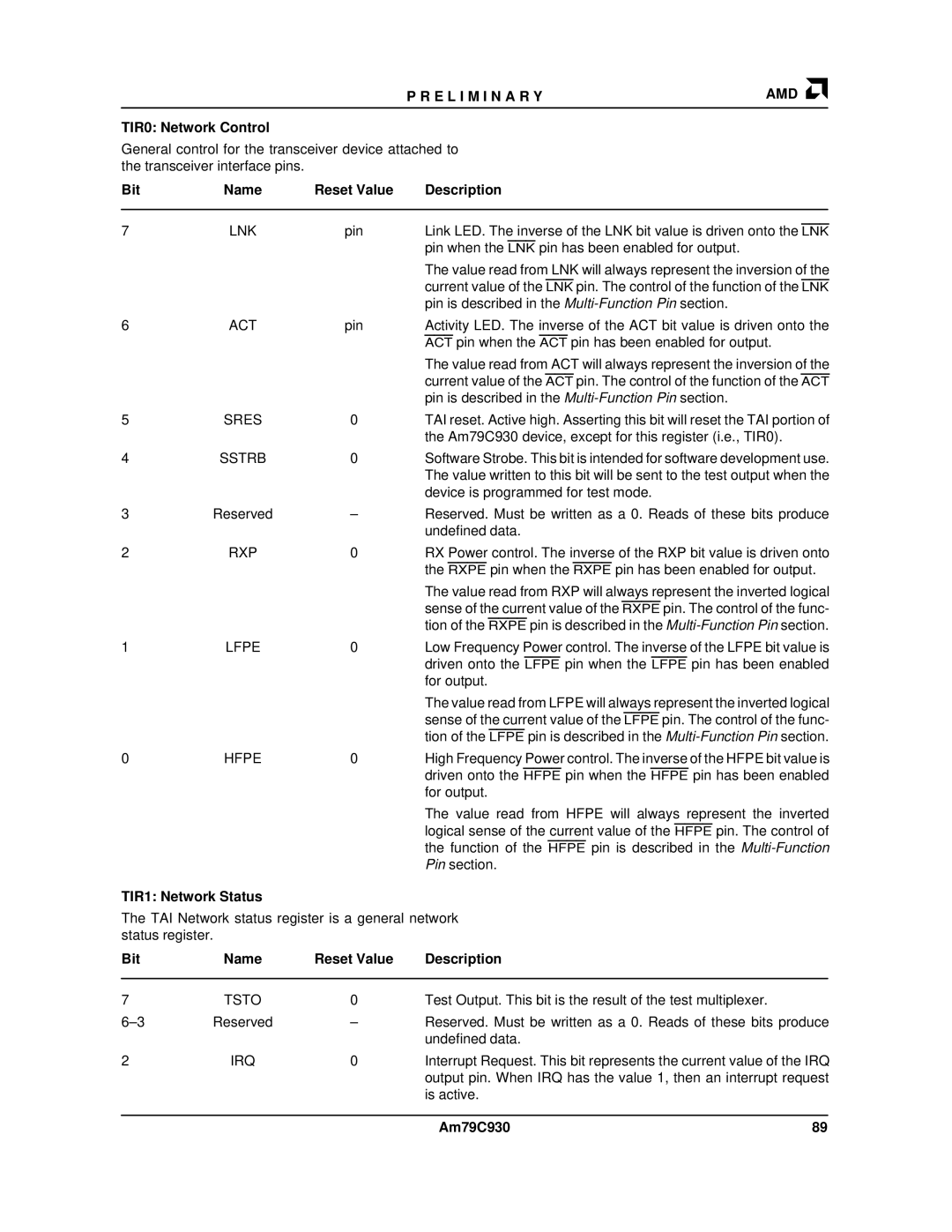
TIR0: Network Control |
|
|
|
| |
General control for the transceiver device attached to |
|
| |||
the transceiver interface pins. |
|
|
|
| |
Bit | Name | Reset Value | Description |
|
|
|
|
|
|
| |
7 | LNK | pin | Link LED. The inverse of the LNK bit value is driven onto the LNK | ||
|
|
| pin when the LNK pin has been enabled for output. |
|
|
|
|
| The value read from LNK will always represent the inversion of the | ||
|
|
| current value of the LNK pin. The control of the function of the LNK | ||
|
|
| pin is described in the |
|
|
6 | ACT | pin | Activity LED. The inverse of the ACT bit value is driven onto the | ||
|
|
| ACT pin when the ACT pin has been enabled for output. | ||
|
|
| The value read from ACT will always represent the inversion of the | ||
|
|
| current value of the ACT pin. The control of the function of the ACT | ||
|
|
| pin is described in the |
|
|
5 | SRES | 0 | TAI reset. Active high. Asserting this bit will reset the TAI portion of | ||
|
|
| the Am79C930 device, except for this register (i.e., TIR0). | ||
4 | SSTRB | 0 | Software Strobe. This bit is intended for software development use. | ||
|
|
| The value written to this bit will be sent to the test output when the | ||
|
|
| device is programmed for test mode. |
|
|
3 | Reserved | – | Reserved. Must be written as a 0. Reads of these bits produce | ||
|
|
| undefined data. |
|
|
2 | RXP | 0 | RX Power control. The inverse of the RXP bit value is driven onto | ||
|
|
| the RXPE pin when the RXPE pin has been enabled for output. | ||
|
|
| The value read from RXP will always represent the inverted logical | ||
|
|
| sense of the current value of the RXPE pin. The control of the func- | ||
|
|
| tion of the RXPE pin is described in the | ||
1 | LFPE | 0 | Low Frequency Power control. The inverse of the LFPE bit value is | ||
|
|
| driven onto the LFPE pin when the LFPE pin has been enabled | ||
|
|
| for output. |
|
|
|
|
| The value read from LFPE will always represent the inverted logical | ||
|
|
| sense of the current value of the LFPE pin. The control of the func- | ||
|
|
| tion of the LFPE pin is described in the | ||
0 | HFPE | 0 | High Frequency Power control. The inverse of the HFPE bit value is | ||
|
|
| driven onto the HFPE pin when the HFPE pin has been enabled | ||
|
|
| for output. |
|
|
|
|
| The value read from HFPE will always represent the inverted | ||
|
|
| logical sense of the current value of the HFPE pin. The control of | ||
|
|
| the function of the HFPE pin is described in the | ||
|
|
| Pin section. |
|
|
TIR1: Network Status |
|
|
|
| |
The TAI Network status register is a general network |
|
| |||
status register. |
|
|
|
| |
Bit | Name | Reset Value | Description |
|
|
|
|
|
|
| |
7 | TSTO | 0 | Test Output. This bit is the result of the test multiplexer. | ||
Reserved | – | Reserved. Must be written as a 0. Reads of these bits produce | |||
|
|
| undefined data. |
|
|
2 | IRQ | 0 | Interrupt Request. This bit represents the current value of the IRQ | ||
|
|
| output pin. When IRQ has the value 1, then an interrupt request | ||
|
|
| is active. |
|
|
|
|
|
|
|
|
|
|
| Am79C930 | 89 | |