P R E L I M I N A R Y | AMD |
|
|
be high assert, such that when the TGAP2 counter expires, the TXMOD pin will be driven to a HIGH logic level.
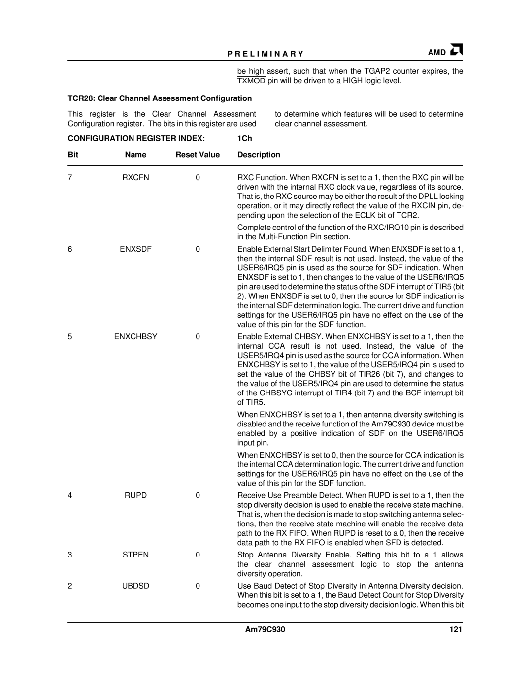
TCR28: Clear Channel Assessment Configuration
This register is the Clear Channel Assessment Configuration register. The bits in this register are used
to determine which features will be used to determine clear channel assessment.
CONFIGURATION REGISTER INDEX: | 1Ch |
|
| ||
Bit | Name | Reset Value | Description |
|
|
|
|
|
|
| |
7 | RXCFN | 0 | RXC Function. When RXCFN is set to a 1, then the RXC pin will be | ||
|
|
| driven with the internal RXC clock value, regardless of its source. | ||
|
|
| That is, the RXC source may be either the result of the DPLL locking | ||
|
|
| operation, or it may directly reflect the value of the RXCIN pin, de- | ||
|
|
| pending upon the selection of the ECLK bit of TCR2. |
|
|
|
|
| Complete control of the function of the RXC/IRQ10 pin is described | ||
|
|
| in the |
|
|
6 | ENXSDF | 0 | Enable External Start Delimiter Found. When ENXSDF is set to a 1, | ||
|
|
| then the internal SDF result is not used. Instead, the value of the | ||
|
|
| USER6/IRQ5 pin is used as the source for SDF indication. When | ||
|
|
| ENXSDF is set to 1, then changes to the value of the USER6/IRQ5 | ||
|
|
| pin are used to determine the status of the SDF interrupt of TIR5 (bit | ||
|
|
| 2). When ENXSDF is set to 0, then the source for SDF indication is | ||
|
|
| the internal SDF determination logic. The current drive and function | ||
|
|
| settings for the USER6/IRQ5 pin have no effect on the use of the | ||
|
|
| value of this pin for the SDF function. |
|
|
5 | ENXCHBSY | 0 | Enable External CHBSY. When ENXCHBSY is set to a 1, then the | ||
|
|
| internal CCA result is not used. Instead, the value of the | ||
|
|
| USER5/IRQ4 pin is used as the source for CCA information. When | ||
|
|
| ENXCHBSY is set to 1, the value of the USER5/IRQ4 pin is used to | ||
|
|
| set the value of the CHBSY bit of TIR26 (bit 7), and changes to | ||
|
|
| the value of the USER5/IRQ4 pin are used to determine the status | ||
|
|
| of the CHBSYC interrupt of TIR4 (bit 7) and the BCF interrupt bit | ||
|
|
| of TIR5. |
|
|
|
|
| When ENXCHBSY is set to a 1, then antenna diversity switching is | ||
|
|
| disabled and the receive function of the Am79C930 device must be | ||
|
|
| enabled by a positive indication of SDF on the USER6/IRQ5 | ||
|
|
| input pin. |
|
|
|
|
| When ENXCHBSY is set to 0, then the source for CCA indication is | ||
|
|
| the internal CCA determination logic. The current drive and function | ||
|
|
| settings for the USER6/IRQ5 pin have no effect on the use of the | ||
|
|
| value of this pin for the SDF function. |
|
|
4 | RUPD | 0 | Receive Use Preamble Detect. When RUPD is set to a 1, then the | ||
|
|
| stop diversity decision is used to enable the receive state machine. | ||
|
|
| That is, when the decision is made to stop switching antenna selec- | ||
|
|
| tions, then the receive state machine will enable the receive data | ||
|
|
| path to the RX FIFO. When RUPD is reset to a 0, then the receive | ||
|
|
| data path to the RX FIFO is enabled when SFD is detected. |
|
|
3 | STPEN | 0 | Stop Antenna Diversity Enable. Setting this bit to a 1 allows | ||
|
|
| the clear channel assessment logic to stop the antenna | ||
|
|
| diversity operation. |
|
|
2 | UBDSD | 0 | Use Baud Detect of Stop Diversity in Antenna Diversity decision. | ||
|
|
| When this bit is set to a 1, the Baud Detect Count for Stop Diversity | ||
|
|
| becomes one input to the stop diversity decision logic. When this bit | ||
|
|
|
|
|
|
|
|
| Am79C930 | 121 | |
