| AMD |
| P R E L I M I N A R Y |
|
|
|
|
1 | RXDRQ | 0 | Receive FIFO DMA Request. This bit represents the current |
|
|
| value of the RXDRQ signal to the DRQ0 input of the 80188 |
|
|
| embedded core. |
0 | TXDRQ | 1 | Transmit FIFO DMA Request. This bit represents the current |
|
|
| value of the TXDRQ signal to the DRQ1 input of the 80188 |
|
|
| embedded core. |
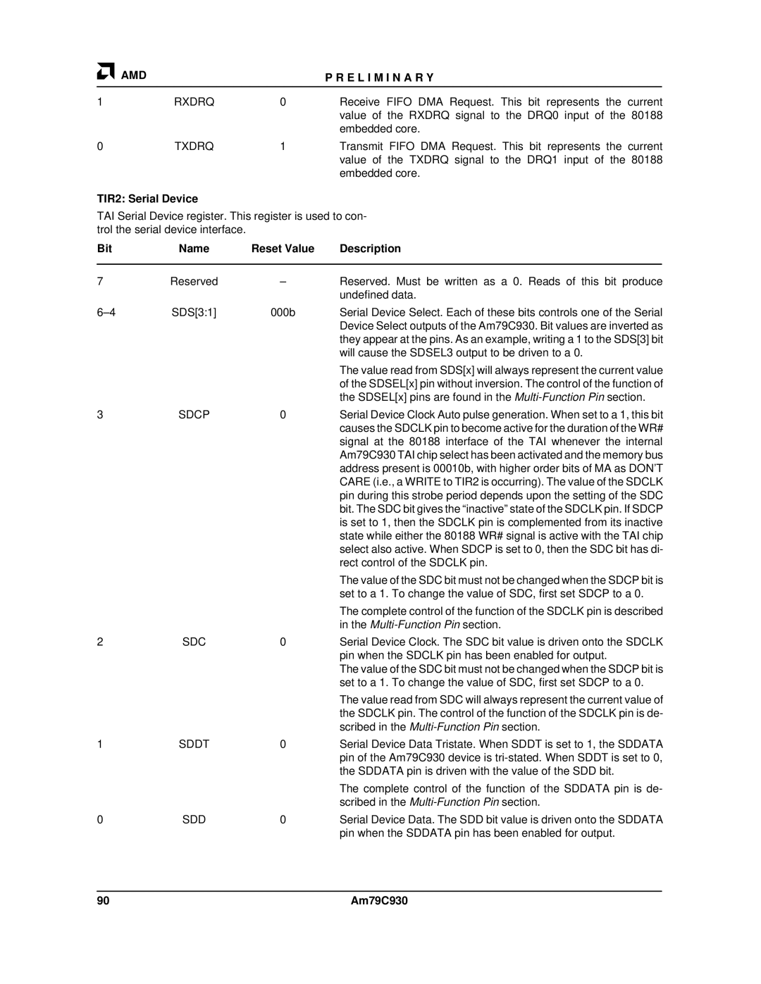
TIR2: Serial Device
TAI Serial Device register. This register is used to con- trol the serial device interface.
Bit | Name | Reset Value | Description | |
|
|
|
|
|
7 | Reserved | – | Reserved. Must be written as a 0. Reads of this bit produce | |
|
|
| undefined data. | |
SDS[3:1] | 000b | Serial Device Select. Each of these bits controls one of the Serial | ||
|
|
| Device Select outputs of the Am79C930. Bit values are inverted as | |
|
|
| they appear at the pins. As an example, writing a 1 to the SDS[3] bit | |
|
|
| will cause the SDSEL3 output to be driven to a 0. | |
|
|
| The value read from SDS[x] will always represent the current value | |
|
|
| of the SDSEL[x] pin without inversion. The control of the function of | |
|
|
| the SDSEL[x] pins are found in the | |
3 | SDCP | 0 | Serial Device Clock Auto pulse generation. When set to a 1, this bit | |
|
|
| causes the SDCLK pin to become active for the duration of the WR# | |
|
|
| signal at the 80188 interface of the TAI whenever the internal | |
|
|
| Am79C930 TAI chip select has been activated and the memory bus | |
|
|
| address present is 00010b, with higher order bits of MA as DON'T | |
|
|
| CARE (i.e., a WRITE to TIR2 is occurring). The value of the SDCLK | |
|
|
| pin during this strobe period depends upon the setting of the SDC | |
|
|
| bit. The SDC bit gives the “inactive” state of the SDCLK pin. If SDCP | |
|
|
| is set to 1, then the SDCLK pin is complemented from its inactive | |
|
|
| state while either the 80188 WR# signal is active with the TAI chip | |
|
|
| select also active. When SDCP is set to 0, then the SDC bit has di- | |
|
|
| rect control of the SDCLK pin. | |
|
|
| The value of the SDC bit must not be changed when the SDCP bit is | |
|
|
| set to a 1. To change the value of SDC, first set SDCP to a 0. | |
|
|
| The complete control of the function of the SDCLK pin is described | |
|
|
| in the | |
2 | SDC | 0 | Serial Device Clock. The SDC bit value is driven onto the SDCLK | |
|
|
| pin when the SDCLK pin has been enabled for output. | |
|
|
| The value of the SDC bit must not be changed when the SDCP bit is | |
|
|
| set to a 1. To change the value of SDC, first set SDCP to a 0. | |
|
|
| The value read from SDC will always represent the current value of | |
|
|
| the SDCLK pin. The control of the function of the SDCLK pin is de- | |
|
|
| scribed in the | |
1 | SDDT | 0 | Serial Device Data Tristate. When SDDT is set to 1, the SDDATA | |
|
|
| pin of the Am79C930 device is | |
|
|
| the SDDATA pin is driven with the value of the SDD bit. | |
|
|
| The complete control of the function of the SDDATA pin is de- | |
|
|
| scribed in the | |
0 | SDD | 0 | Serial Device Data. The SDD bit value is driven onto the SDDATA | |
|
|
| pin when the SDDATA pin has been enabled for output. | |
90 | Am79C930 |