|
|
| P R E L I M I N A R Y |
|
| AMD | |||
|
|
|
|
|
|
|
|
| |
|
|
|
| In addition, the USER5/IRQ4 pin may be used to produce interrupts | |||||
|
|
|
| to the 80188 embedded controller. This capability is controlled by | |||||
|
|
|
| the ENXCHBSY bit of TCR28 and the CHBSYCU bit of TIR5 and | |||||
|
|
|
| operates independently of the bits mentioned above. | |||||
|
|
|
| The control of the function of the USER5/IRQ4 pin is described in | |||||
|
|
|
| the |
|
|
| ||
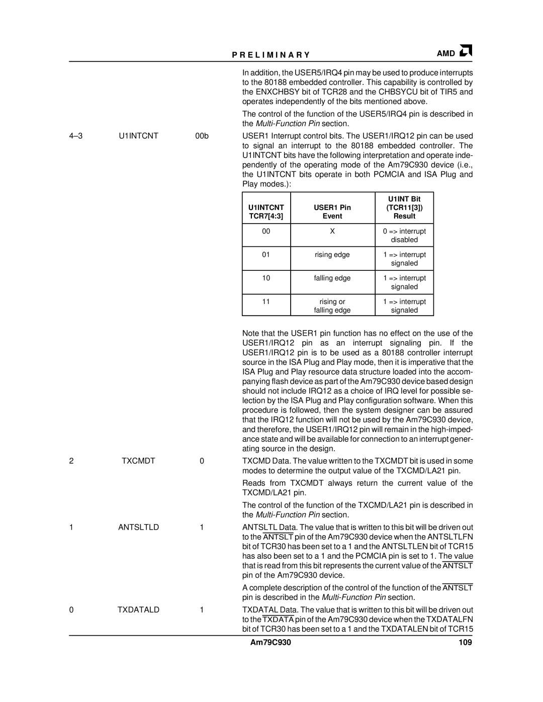
U1INTCNT | 00b | USER1 Interrupt control bits. The USER1/IRQ12 pin can be used | |||||||
|
|
|
| to signal an interrupt to the 80188 embedded controller. The | |||||
|
|
|
| U1INTCNT bits have the following interpretation and operate inde- | |||||
|
|
|
| pendently of the operating mode of the Am79C930 device (i.e., | |||||
|
|
|
| the U1INTCNT bits operate in both PCMCIA and ISA Plug and | |||||
|
|
|
| Play modes.): |
|
|
|
| |
|
|
|
|
|
|
|
|
| |
|
|
|
|
|
|
| U1INT Bit |
|
|
|
|
|
| U1INTCNT |
| USER1 Pin | (TCR11[3]) |
| |
|
|
|
| TCR7[4:3] |
| Event | Result |
| |
|
|
|
|
|
|
|
|
| |
|
|
|
| 00 |
| X | 0 => interrupt |
|
|
|
|
|
|
|
|
| disabled |
| |
|
|
|
|
|
|
|
|
| |
|
|
|
| 01 |
| rising edge | 1 => interrupt |
|
|
|
|
|
|
|
|
| signaled |
| |
|
|
|
|
|
|
|
|
| |
|
|
|
| 10 |
| falling edge | 1 => interrupt |
|
|
|
|
|
|
|
|
| signaled |
| |
|
|
|
|
|
|
|
|
| |
|
|
|
| 11 |
| rising or | 1 => interrupt |
|
|
|
|
|
|
|
| falling edge | signaled |
| |
|
|
|
|
|
|
|
| ||
|
|
|
| Note that the USER1 pin function has no effect on the use of the | |||||
|
|
|
| USER1/IRQ12 pin as an interrupt signaling pin. If the | |||||
|
|
|
| USER1/IRQ12 pin is to be used as a 80188 controller interrupt | |||||
|
|
|
| source in the ISA Plug and Play mode, then it is imperative that the | |||||
|
|
|
| ISA Plug and Play resource data structure loaded into the accom- | |||||
|
|
|
| panying flash device as part of the Am79C930 device based design | |||||
|
|
|
| should not include IRQ12 as a choice of IRQ level for possible se- | |||||
|
|
|
| lection by the ISA Plug and Play configuration software. When this | |||||
|
|
|
| procedure is followed, then the system designer can be assured | |||||
|
|
|
| that the IRQ12 function will not be used by the Am79C930 device, | |||||
|
|
|
| and therefore, the USER1/IRQ12 pin will remain in the | |||||
|
|
|
| ance state and will be available for connection to an interrupt gener- | |||||
|
|
|
| ating source in the design. |
|
|
| ||
2 | TXCMDT | 0 |
| TXCMD Data. The value written to the TXCMDT bit is used in some | |||||
|
|
|
| modes to determine the output value of the TXCMD/LA21 pin. | |||||
|
|
|
| Reads from TXCMDT always return the current value of the | |||||
|
|
|
| TXCMD/LA21 pin. |
|
|
|
| |
|
|
|
| The control of the function of the TXCMD/LA21 pin is described in | |||||
|
|
|
| the |
|
|
| ||
1 | ANTSLTLD | 1 |
| ANTSLTL Data. The value that is written to this bit will be driven out | |||||
|
|
|
| to the ANTSLT pin of the Am79C930 device when the ANTSLTLFN | |||||
|
|
|
| bit of TCR30 has been set to a 1 and the ANTSLTLEN bit of TCR15 | |||||
|
|
|
| has also been set to a 1 and the PCMCIA pin is set to 1. The value | |||||
|
|
|
| that is read from this bit represents the current value of the ANTSLT | |||||
|
|
|
| pin of the Am79C930 device. |
|
|
| ||
|
|
|
| A complete description of the control of the function of the ANTSLT | |||||
|
|
|
| pin is described in the | |||||
0 | TXDATALD | 1 |
| TXDATAL Data. The value that is written to this bit will be driven out | |||||
|
|
|
| to the TXDATA pin of the Am79C930 device when the TXDATALFN | |||||
|
|
|
| bit of TCR30 has been set to a 1 and the TXDATALEN bit of TCR15 | |||||
|
|
|
|
|
|
|
|
|
|
|
|
|
| Am79C930 |
| 109 |
| ||