Software Version
Page
Table of Contents
Buffering
Hunt Groups
Intelligent Multicast
Document No -300090, Issue Vii
IP-RIP
Layer 3 Forwarding Cache
Logging
Policy
Power Cool RAM
Series QoS
SSH
Switch Fabric
Temperatures
User Interface
Vrrp
Mode Description To Access Prompt
Command Mode Summaries
Main Command Mode Summaries
Mode To Access Prompt Displayed To Exit
Entering and Exiting the Command Modes
Entering and Exiting the Command Modes
Routerprotocol #
Basic Functions
Command Description Example
Basic Functions
History Buffer Key Sequence
Command Syntax Conventions
Convention Description
Keys Function
Accessing the CLI
Accessing the CLI Using Telnet
Chapter
AFT
Overview
Parameters, Keywords, Arguments
Configure# clear aft instance invalid-learned-entries vlan
Clear aft instance invalid-learned-entries vlan
Name Definition
Configure# clear aft instance learned-entries vlan
Clear aft instance learned-entries vlan
Age-time-value
Configure# set aft agetime
Set aft agetime
Threshold-value
Configure# set aft auto-sizing-threshold
Set aft auto-sizing-threshold
To Delete
To Configure
Set aft entry
Entry-priority
Enter
Da-priority aft
Set aft instance vlan auto-increment
Set aft instance vlan hash-table-size
Super-age-time
Configure# set aft super-agetime
Set aft super-agetime
Value
Show aft config
Show aft config
Show aft entry
Show aft entry
Show aft instance
Show aft instance
10. Parameters, Keywords, Arguments
Vlan
Appletalk
To Disable
Appletalk access-group
To Enable
Config-ifserial0#appletalk access-group
Appletalk access-list
Configuration# no appletalk access-list
Appletalk address
Name Definition
Appletalk admin-state
Config-ifserial0#appletalk admin-state down
Appletalk cable-range
Sample Output
Appletalk echo
Syntax
Appletalk mac-format
To Restore Default
Config-ifserial0#appletalk mac-format ethv2
Appletalk routing
Appletalk static cable-range
Configure# appletalk static cable-range 110-120 to 1.5 zone
Adams
Appletalk vlan
Appletalk zone
Clear appletalk arp
11. Parameters, Keywords, Arguments
12. Parameters, Keywords, Arguments
Config# clear appletalk route
Clear appletalk route
Network
Clear appletalk traffic
Ping appletalk
13. Parameters, Keywords, Arguments
Show appletalk access-lists
Show appletalk access-list
Show appletalk arp
Show appletalk arp
14. Parameters, Keywords, Arguments
Show appletalk globals
Show appletalk globals
Show appletalk interface brief jerry
Show appletalk interface
15. Parameters, Keywords, Arguments
Interface
Show appletalk nbp
Show appletalk nbp
Show appletalk route
Show appletalk route
16. Parameters, Keywords, Arguments
Starting-range
Show appletalk static cable-range
Show appletalk static cable-range
17. Parameters, Keywords, Arguments
Starting
Show appletalk traffic
Show appletalk traffic
Show appletalk zone Zone1
Show appletalk zone
18. Parameters, Keywords, Arguments
Chapter
Buffering
Spec
Set buffering fabric-port age-timer
Fabric-port
Fabric-port-spec
Set buffering fabric-port hipri-alloc
Alloc
Set buffering fabric-port hipri-service-ratio
Service-ratio 9999-to-1
Set buffering fabric-port pri-threshold
Set buffering port age-timer
Set buffering port hipri-alloc
Mod-port-spec
Set buffering port hipri-service-ratio
15-to-1
Set buffering port pri-threshold
Show buffering fabric-port
Show buffering fabric-port 4/1-4/10
Show buffering port
Show buffering port 6/19
Chapter
Console
Configure# set console baud
Set console baud
Configure# set console databits
Set console databits
Configure# set console flowcontrol none
Set console flowcontrol
Configure# set console initcmd AT&D0S0=1
Set console initcmd
Configure# set console parity even
Set console parity
Configure# set console stopbits
Set console stopbits
Configure# set console transfer ppp
Set console transfer ppp
Configure# set console type ppp
Set console type
Show console
Show console
DNS
Configure# ip domain-lookup
Ip domain-lookup
Configure# ip name-server
Ip name-server
Configure# ip domain-list avaya.com
Ip domain-list
Configure# ip domain-name avaya.com
Ip domain-name
Show host
Dvmrp
Ip dvmrp
Dvmrp interface metric
Config-ifboston#ip dvmrp interface-metric
Ip dvmrp interface-metric
Config-ifboston#ip dvmrp interface type IPIPTunnel
Ip dvmrp interface type
Default
Ip dvmrp min-route-flash-update
To Restore
Ip dvmrp neighbor-probe-interval
Ip dvmrp neighbor-timeout
Ip dvmrp prune-message-lifetime
Interface
Configure if1# ip dvmrp remote-tunnel-address
Ip dvmrp remote-tunnel-address
Ip dvmrp route-limit
Thousand, five hundred
Ip dvmrp stats-reset
Ip dvmrp timers basic
Configure if1# ip multicast prune-source host-addr
Ip multicast prune-source
Ip multicast ttl-threshold
Only outbound broadcasts are accepted
Router dvmrp
Show ip dvmrp
Show ip dvmrp
Show ip dvmrp designated forwarders
For ip address 20.0.4.0 and mask
Show ip dvmrp downstream dependent routers
Neighbor routers for ip address 20.0.4.0 and mask
Show ip dvmrp forwarding cache
Show ip dvmrp forwarding cache
Show ip dvmrp interface
Show ip dvmrp interface
Show ip dvmrp interface neighbors
Show ip dvmrp interface neighbors
Show ip dvmrp routes
Show ip dvmrp routes
Hunt Groups
Set huntgroup
Set huntgroup auto-flush
Huntgroup-name
Configure# set huntgroup hg1 redistribute
Set huntgroup redistribute
Set huntgroup internal-error-shutdown
Configure# set huntgroup internal-error-shutdown enable
Show huntgroup
Show huntgroup
Show huntgroup detailed
Show huntgroup detailed
Show huntgroup internal-error-config
Configure# show huntgroup internal-error-config
Igmp
Ip igmp
Following example sets the maximum number of Igmp groups on
Config-ifboston#ip igmp max-groups
Ip igmp max-groups
Interface labelled Boston to
Config-ifboston#ip igmp process-leaves
Ip igmp process-leaves
Ip igmp querier
Ip igmp querier-timeout
Config-ifboston#ip igmp querier-timeout
Ip igmp query-interval
Ip igmp query-max-response-time
Ip igmp query-timeout
Config-ifboston#ip igmp query-timeout
Ip igmp robustness
Ip igmp version
Ip mtrace
Ip mtrace
Source
Mtrace
# mtrace 10.0.2.129 10.0.4.177
Destination
Configure# no router igmp
Router igmp
Show ip igmp groups
Show ip igmp groups
Show ip igmp interface
Show ip igmp interface
Show ip igmp statistics
Show ip igmp statistics
Chapter
Intelligent Multicast
Chapter
Configure# clear cgmp statistics
Clear cgmp statistics
Configure# clear igmp snooping statistics
Clear igmp-snooping statistics
Port
Clear intelligent-multicast client-port
Session-id
Clear intelligent-multicast router-port
All VLANs bound to port 3/4
Configure# clear intelligent-multicast session
Clear intelligent-multicast session
Group-address
Clear intelligent-multicast static-client-port
Vlan all port 3/2
Mac-address
Clear intelligent-multicast static-session
All
Configure# clear lgmp client statistics
Clear lgmp client statistics
Configure# clear lgmp server statistics
Clear lgmp server statistics
Configure# set cgmp enable
Set cgmp
Configure# set igmp-snooping enable
Set igmp-snooping
Configure# set intelligent-multicast enable
Set intelligent-multicast
Set intelligent-multicast client-leave-processing
Set intelligent-multicast client-port-pruning
Set intelligent-multicast client-port-pruning time
Minutes
Set intelligent-multicast router-port
Following example adds a multicast router port
Set intelligent-multicast router-port-pruning
Set intelligent-multicast router-port-pruning time
Configure# set intelligent-multicast session-pruning disable
Set intelligent-multicast session-pruning
Configure# set intelligent-multicast session-pruning time
Set intelligent-multicast session-pruning time
Vlan 4 port 3/11
Configure# set intelligent-multicast static-client-port
Set intelligent-multicast static-client-port
Set intelligent-multicast static-session
Vlan name adams
Configure# set lgmp client enable
Set lgmp client
Configure# set lgmp server disable
Set lgmp server
Set lgmp server priority
Configure# set lgmp server proxy enable
Set lgmp server proxy
Rrt-seconds
Configure# set lgmp server router-report-time
Set lgmp server router-report-time
Rv-val
Configure# set lgmp server robust-variable
Set lgmp server robust-variable
Show cgmp statistics
Show cgmp statistics
Show igmp-snooping statistics
Show igmp-snooping statistics
Show intelligent-multicast client-port
Show intelligent-multicast client-port
19. Parameters, Keywords, Arguments
Show intelligent-multicast configuration
Show intelligent-multicast configuration
Show intelligent-multicast router-port
Show intelligent-multicast router-port
Show intelligent-multicast session
Show intelligent-multicast session
20. Parameters, Keywords, Arguments
Show intelligent-multicast static-client 225.1.1.2 vlan all
Show intelligent-multicast static-client
21. Parameters, Keywords, Arguments
Show intelligent-multicast static-session
Show intelligent-multicast static-session
Show lgmp client statistics
Show lgmp client
22. Parameters, Keywords, Arguments
Show lgmp server statistics
Show lgmp server
23. Parameters, Keywords, Argument
11 IP
Chapter
Document No -300090, Issue 11-3
Arp
To Create
Arp timeout
Configure# clear arp-cache
Clear arp-cache
Clear ip route
Local-tcp-port
Clear tcp
Local-ip-address
Remote-ip-address
Interface
To Remove
Ip address
To Assign
Ip admin-state
Ip bootp-dhcp agent-info
Ip bootp-dhcp circuit-info
Ip bootp-dhcp relay
To Add
Ip bootp-dhcp server
IP address of the BOOTP/DHCP server for which you want to
Address Add an entry
Ip default-gateway
Default gateway Configure# ip default-gateway
Config-ifboston#ip directed-broadcast
Ip directed broadcast
Command removes the domain name
Document No -300090, Issue 11-19
Ip domain-name
10. Keywords, Arguments, and Options
Configure# ip http port
Ip http
Ip irdp
Ip irdp holdtime
Irdp maxadvertinterval
Ip irdp minadverinterval
Ip irdp multicast
Ip irdp preference
Ip mac-format
Ip max-arp-entries
Routing table as
Configure# ip max-route-entries
Ip max-route-entries
Configure# ip multicast-routing
Ip multicast-routing
Following example adds the DNS address
Ip netbios-rebroadcast
Configure# ip netmask-format bitcount
Ip netmask-format
Ip proxy-arp
Ip proxy-arp-default-route
Configure# ip proxy-arp-default-route
Configure# ip proxy-arp-limit
Ip proxy-arp-limit
Ip redirects
Ip reset-stats
Configure# ip reset-stats
Ip route
Configure# ip route 10.10.10.1 255.255.0.0 10.15.1.1 low
Configure# ip route-preference rip
Ip route-preference
Ip routing
Config-ifboston#ip routing-mode Mgmtonly
Ip routing-mode
Keyword, Argument, or Definition Option
Ip short-lived
23. Keywords, Arguments, and Options
P580 and P882
Configure# no ip source-route
Ip source-route
24. Parameters, Keywords, Arguments
Seconds Configure# ip telnet inactivity-period
Ip telnet inactivity-period
25. Parameters, Keywords, Arguments
Configure# ip telnet port
Ip telnet
Vlan-id ID of the Vlan Vlan-name Name of the Vlan
Ip vlan
26. Parameters, Keywords, Arguments
Ping
27. Parameters, Keywords, Arguments
To Delete an Entry that
Redistribute
To Redistribute Routes to
Redistributes Routes to
Access-list
28. Parameters, Keywords, Arguments
Show arp
Show arp
29. Parameters, Keywords, Arguments
Ip-addr
Show hosts
Show hosts
Show ip arp
Show ip arp
30. Parameters, Keywords, Arguments
Show ip interface boston
Show ip interface
31. Parameters, Keywords, Arguments
Interface-name
Show ip irdp
Show ip irdp
32. Parameters, Keywords, Arguments
Displays IP redistribute list entries
Show ip redistribute
User
Show ip redistribute
Show ip route static
Show ip route
33. Parameters, Keywords, Arguments
Show ip route summary
Show ip short-lived
Show ip traffic
Show ip traffic
Show tcp configuration
Show tcp configuration
Show tcp connections
Show tcp statistics
Show tcp statistics
Displays TCP connection statistics
Show udp statistics
IP-RIP
Default-metric
Labeled boston to
Ip rip authentication key
To Clear
Ip rip authentication mode
Ip rip default-route-mode
Config-ifboston#ip rip poison-reverse
Ip rip poison-reverse
Config-ifboston#ip rip receive version
Ip rip receive version
Config-ifboston#ip rip send version
Ip rip send version
Config-ifboston#ip rip send-receive-mode listen-only
Ip rip send-receive-mode
Network
Output-delay
Router rip
Timers basic
Triggered updates
Show ip rip statistics
Show ip rip statistics
Chapter
13 IPX
Chapter
Configure# clear ipx route
Clear ipx route
Service-type
Clear ipx service
Configure# clear ipx service
Service-name
Ipx advertise-default-route-only
Config-ifboston# ipx advertise-default-route-only
Ipx default-route
Configure# ipx default-route
Ipx delay
Ipx down
Ipx gns-reply-disable
Config-ifboston# ipx gns-reply-disable
Ipx gns-response-delay
Ipx network
Config-ifboston#ipx network 2 encapsulation snap
Ipx output-rip-delay
Ipx output-sap-delay
Ipx rip
Ipx rip-filter
Filter-hops
Config-ifboston#ipx rip-filter 5 2 3 both allow 10000
Filter-ticks
Config-ifboston#ipx rip-max-packetsize
Ipx rip-max-packetsize
Ipx rip-multiplier
Ipx route
Configure
Configure# ipx route 50 100.02e03b004563
Ipx router
Ipx routing
Ipx sap
Config-ifboston#ipx sap-max-packetsize
Ipx sap-max-packetsize
Ipx sap-multiplier
Ipx sap-name-filter
Config-ifboston#ipx sap-name-filter 2 netbios 1 both allow
Ipx sap-network-filter
Config-ifboston#ipx sap-network-filter 1 3 2 both allow
Ipx send-receive-mode
Ipx send-triggered-updates
Ipx service
Following example adds a static service to the service table
Ipx type-20-propagation
Ipx update interval
Configure To Disable
Ipx vlan
Show ipx cache command
Show ipx cache
Intf-name
Enter the show ipx interface command
Show ipx interface
Show ipx rip statistics
Show ipx rip-filter
Show ipx route command
Show ipx route
Show ipx sap statistics
Show ipx sap-name-filter
Show ipx sap-network-filter
Show ipx service
Show ipx service command
Show ipx traffic command
Show ipx traffic
Layer 3 Forwarding Cache
Configure# ip multicast route-cache aging
Ip multicast route-cache aging
Ip multicast route-cache hash-mode
Ip multicast route-cache max-size
Following example enables IP multicast route cache max size
Entries Configure# ip multicast route-cache max-size
Ip multicast route-cache readd-timeout
Timeout-interval
Configure# ip multicast route-cache readd-timeout
Ip multicast route-cache update-timeout
Ip-multicast-period
Configure# ip unicast route-cache aging
Ip unicast route-cache aging
Ip unicast route-cache hash-mode
Configure To Restore
Configure# ip unicast route-cache hash-mode da-only
10000 Configure# ip unicast route-cache max-size
Ip unicast route-cache max-size
Configure# ip unicast route-cache update-timeout
Ip unicast route-cache update-timeout
Command and sets it to 60 seconds
Configure# ipx route-cache aging disabled
Ipx route-cache aging
Configure# ipx route-cache hash-mode sa-da
Ipx route-cache hash-mode
Configure# ipx route-cache max-size
Ipx route-cache max-size
This command restores the default of 120 seconds
Ipx route-cache update-timeout
Global Configuration
Configure# ipx route-cache update-timeout
Show ip multicast cache
Show ip multicast cache
Show ip unicast cache
Show ip unicast cache
Show ipx cache
Ldap
Ldap execution-option
Error
Configure# ldap execution-option ignore-errors
To Stop
Search base default is ou=Devices, ov=CajunRules, o=Avaya
Ldap search-base
Ldap server primary
Ldap server secondary
Show ldap
Show ldap
Logging
Logging clear
Logging console
Parameters, Keywords, Arguments
Document No -300090, Issue 16-5
Logging history
Syntax
Document No -300090, Issue 16-7
Systems
Configure# logging history size
Logging history size
Logging protocol event
Configure# logging protocol event ldap fault
Configure# logging shutdown size
Logging shutdown size
Logging traps
Configure# logging traps switchfabric
Set syslog
Set syslog facility
Name
Logging
Systems
Set syslog serverip
Severity Level Description
Set syslog severity
Syslog Severity Levels
Show alarms
Show alarms
Num-events
Show logging
Show logging shutdown
Show syslog buffer
Show syslog config
Module
Mod-num
Reset-module
Configure# reset-module
Mod-name
Configure# set module name 3 MIS dept module
Set module name
Set module notes
Mod-notes
Show module
Show module
Show module inventory
Show module-inventory
Nedr and Iedr
For all ports in hunt groups
Set internal-error-threshold
Parameters, Keywords, Argument
Mod-num mod
Set port internal-error-shutdown
Configure# set port internal-error-shutdown 3 enable
Swport-spec
Set port network-error-detection
Configure# set port network-error-detection 3/1-5
Global Iedr threshold setting
Show port internal-error-config
Show port network-error detection
Chapter
Ospf
Chapter
Area
Area ase-filter
Area default-cost
Area nssa
Following command sets nssa on the indicated area
Following command removes nssa from the indicated area
Area range
Area stub
On the indicated Ospf area
Configure routerospf# area 2.0.0.0 translate-nssa-to
Area translate-nssa-to-external
External
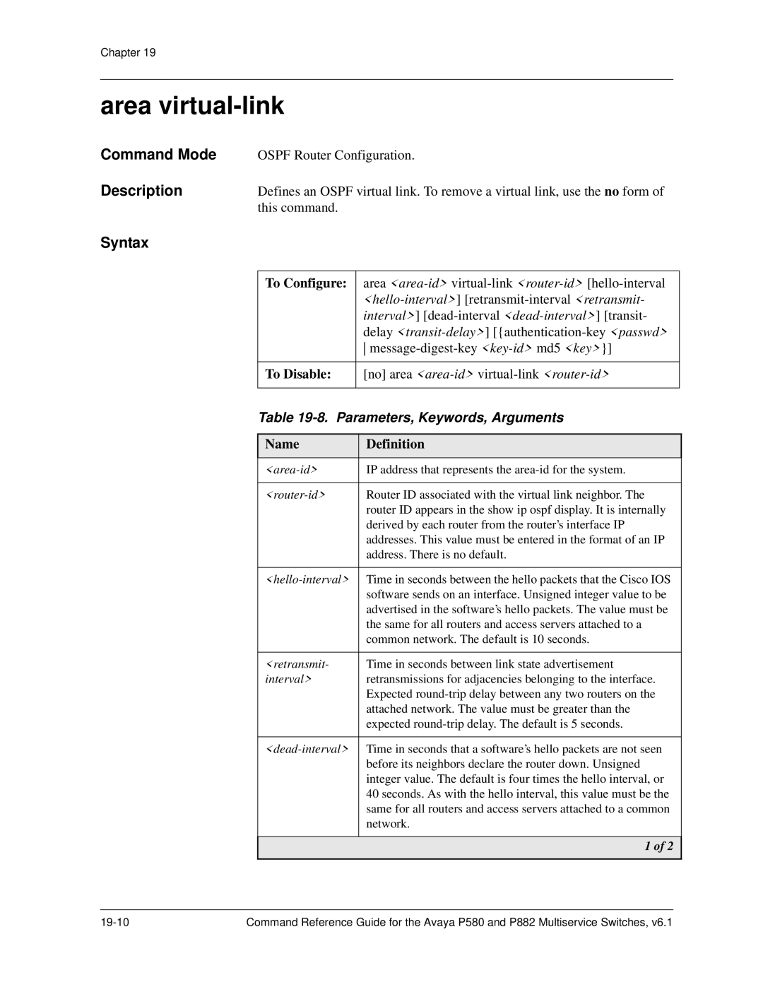
Area virtual-link
Ospf
Ip ospf as-boundary-router
Ip ospf authentication-key
Password
Config-ifintf3#ip ospf auto-vlink-create
Ip ospf auto-vlink-create
Ip ospf cost
Ip ospf dead-interval
Configure# ip ospf ext-route-metric rip type2
Ip ospf ext-route-metric
Config-ifintf3#ip ospf hello-interval
Ip ospf hello-interval
Configure# ip ospf max-paths
Ip ospf max-paths
With a key ID of 155, and a key labeled jerry
Config-ifintf3#ip ospf message-digest-key 155 md5 jerry
Ip ospf message-digest-key md5
Configure# ip ospf packet tracing
Ip ospf packet tracing
Ip ospf poll interval
Ip ospf reset-stats
Configure# ip ospf reset-stats
Ip ospf retransmit-interval
Ip ospf router-id
Following command sets the router id for interface 123 to
Config-if123#ip ospf router-id
Ip ospf transmit-delay
Seconds Config-if123#ip ospf transmit-delay
Area-id Area ID for the interface
Disable
Network area
Passive-interface
Router ospf
Show ip ospf
Show ip ospf
Show ip ospf database
Show ip ospf database
Show ip ospf interface
Show ip ospf interface intf5
Show ip ospf neighbor
Show ip ospf neighbor
23. Parameters, Keywords, Arguments
Neighbor-id
Show ip ospf stats
Show ip ospf stats
Configure# show ip ospf virtual-link
Show ip ospf virtual-links
Configure# timers lsa-group-pacing
Timers lsa-group-pacing
Following command sets the LSA timers to
Timers spf
Chapter
Policy
Access-list
Parameters, Keywords, and Arguments
Source-wildcard
Protocol-id
Source-ip-addr
Host source-ip-addr
Sample Standard ACL Rules
Enter
Extended ACL Rules
Sample Extended ACL Rules
Document No -300090, Issue 20-7
Systems
Permit 192.168.10.10
Ip access-group
Deny
Configure# ip access-group fwdrules
Ip access-list
Ip acl-logging
Keywords, Arguments, and Options
Ip acl-logging logging-interval
Time-in-seconds
Show access-group
Show access-lists
Show access-lists
Following command displays the access lists
Show acl-match-timer
Access-list-name
Show ip access-lists
Show ip access-lists
Chapter
Port
Chapter
Clear port counters
Configure# clear port counters
Configure# clear port counters 5/7
Set port 3com-mapping-table
Set port allow-learning
Set port auto-flush
Set port auto-negotiation
Set port auto-negotiation-duplex-advertisement
Set port auto-negotiation-flow-control- advertisement
Set port auto-negotiation-speed-advertisement
Set port auto-vlan-create
Set port category
Set port disable
Configure# set port duplex 5/7-11 full-duplex
Set port duplex
Set port edge admin state
Set port enable
Control with aggressive backoff for specified fast
Configure# set port flow-control 3 enable-receive-only
Set port flow-control
Ethernet ports
Configure# set port frame-tags 3/2,5/7-11 use
Set port frame-tags
Configure# set port huntgroup 5/1 huntgroupsales
Set port huntgroup
18. Parameters, Keywords, Argument
Set port intrusion-trap
Set port intrusion-trap-timer
Set port known-mode
Set port mirror
Port that has 2 fabric ports
Sampling always piggyback-port 4/4
Set port mirror Fabricmode2
Parameter Definition
Module Port ranges that you can mirror
24. Port Ranges for Fabric Mode 2 Port Mirroring
Parameter Definition
Systems
Spec Port-name
Configure# set port name 3/2 Really fast port
Set port name
26. Parameters, Keywords, Argument
Document No -300090, Issue 21-31
Configure# set port pace-priority-mode 3,5/7-11 enable
Set port pace-priority-mode
Set port point-to-point admin status
Set port rate-limit-burst-size
Set port rate-limit-mode
Set port rate-limit-rate
Set port-redundancy
Set port-redundancy name
Set port remote-fault-detect
Set port spanning-tree-mode
34. Parameters, Keywords, Arguments
Set port speed
35. Parameters, Keywords, Arguments
Set port trunking-format
36. Parameters, Keywords, Arguments
Set port vlan
37. Parameters, Keywords, Arguments
Set port vlan-binding-method
38. Parameters, Keywords, Arguments
39. Parameters, Keywords, Arguments
Configure# set port vtp-snooping 3/2,5/7-11 enable
Set port vtp-snooping
Show port
Show port
40. Parameters, Keywords, Arguments
Show port counters
41. Parameters, Keywords, Arguments
Show port mirror
Show port mirror
42. Parameters, Keywords, Arguments
Show port mirror Fabricmode2
Show port mirror Fabricmode2
Show port physical
Show port physical
43. Parameters, Keywords, Arguments
Show port status
Show port status
44. Parameters, Keywords, Arguments
Show port redundancy
45. Parameters, Keywords, Arguments
Power Cool RAM
Show system fans
Show system fans
Show system power
Show system power
Show system ram
Show system ram
23 80-Series QoS
An ACL Rule Or ACL
Dscp
Dscp
Parameters, Keywords, Arguments
Examples Standard ACL Rules
Diffserv mask 10.10.60.0
Examples Extended ACL Rules
Diffserv mask host
MyAccessList2 4 permit remark l2
P550R and P880, 80-series modules only
Reset port queue counters
Reset port queue counters 3 ingress
Vlan-name port-binding filter forward mod-port
Priority that you want to assign to the source
Examples set aft entry
Binding forward 3/1 sa-priority aft
Binding forward 3/1 da-priority
Dscp-end-range
Set diffserv plp
Dscp-start-range
Configure# set diffserv priority 7 dscp 15
Set diffserv priority
Configure# set port default-priority 3
Configure# set port default-priority 3/1-5
Configure# set port default-priority 3/1-5,6/1
Set port ignore-tag-priority
Configure# set port ignore-tag-priority 3/1-5,6/1 on
Configure# set port ignore-tag-priority 3 on
Configure# set port ignore-tag-priority 3/1-5 off
802.1p tag priority
Set port mask-diffserv
Configure# set port mask-diffserv 3 on
Set port police
Configure# set port police 3 all-ports
Set port queue service cbq
Set port queue service cbwfq
Series QoS
Set port queue service strict-priority
Configure# set port queue service 5/1-12 strict-priority
Set port queue service wfq
Set port use-diffserv
Configure# set port use-diffserv 6/4-12 on
Show diffserv table
Show diffserv table
Show port
Show port police
Show port queue buffer
Show port queue counters
Show port queue counters 3 all
Show port queue service
Radius
Set radius authentication
Configure# set radius authentication enable
Configure# clear radius authentication group
Set radius authentication group
Configure# set radius authentication group avaya switches
Configure# clear radius authentication realm
Set radius authentication realm
Configure# set radius authentication realm avaya
Set radius authentication retry-number
Set radius authentication retry-time
Set radius authentication server
Configure# set radius authentication source-ip
Set radius authentication source-ip
Following command sets the source IP address to
Required enabled
Set radius authentication switch-service-type- required
Configure# set radius authentication switch-service-type
Set radius authentication udp-port
Configure# set radius authentication udp-port
Show radius authentication
Configure# show radius authentication
Chapter
Snmp
Snmp-server
Community
Snmp-server atm-community
Field Definition
Slot
Snmp-server community
Groupname
Snmp-server contact
Snmp-server engineid
Command Mode Description
Snmp-server group
Systems
Snmp-server location
Snmp-server notify
Snmp-server password
Switch prompts you to enter the new password or passwords.
Snmp-server user
HMAC-MD5
Document No -300090, Issue 25-13
Snmp-server view
Show snmp
Show snmp community
Show snmp engineid
Displays the currently configured engine ID of the switch
Show snmp engineid
Groupname Group for which you want to view Configuration
Show snmp group
Username User for which you want to view Configuration
Show snmp user
Show snmp view
Viewname
26 SSH
Clear ssh
Ends an SSH session
Ip ssh
Tcp-port
Ssh
Keyword, Argument or Definition Option
Username
Ssh keygen
Generates an SSH server key
Ssh timeout
Show ssh
Sample output of the show ssh config command is as follows
27 SSL
Ip https
Show ssl cert
Subject Public Key Info
128aea193294d0d51b
Show ssl certreq
3f670a56708675aefcba42726425a84ba910
52d1
Show ssl ciphers
Show ssl config
Ssl backcert
Ssl certreq
Keyword, Argument or Option Definition
Ssl restart
Ssl selfcert
Rapid Spanning Tree Protocol
Set port edge admin state
Document No -300090, Issue 28-3
Enables or disables Spanning Tree on a port
Set port spantree force-protocol-migration
Systems
Set port spantree priority
Systems
Tree, in User Guide for the Avaya P580 and P882
Multiservice Switches, Software Version
Set spantree
Spanning Tree, in User Guide for the Avaya P580 and P882
Configure# set spantree disable 802.1D
P550R, P580, P880,and P882
Set spantree config
Configure# set spantree config ieee
Set spantree default-path-cost
Software Version
Set spantree fwddelay
Configure# set spantree fwddelay 12 802.1D
Set spantree hello
Set spantree hold-count
Set spantree maxage
Configure# set spantree maxage 25 802.1D
Set spantree portcost
Set spantree portcost mod-swport-range ...,mod-swport-range
Configure# set spantree portcost 5/1 15 802.1D
Set spantree priority
Systems
Set spantree version
Show spantree
User Guide for the Avaya P580 and P882 Multiservice
Switches, Software Version
Show spantree all
Show spantree blocked
Show spantree config
Show spantree config
Show spantree port
Show spantree port vlan 802.1D
Show spantree version
Switch Fabric
Set fabric configure-redundant-hardware
Configure# set fabric configure-redundant-hardware disable
Set fabric enable-redundant-element
Set fabric toggle-active-controller
Show fabric status
Show fabric status
Chapter
System
Chapter
System
Boot system flash
Configure# boot system flash cardapp2
Calendar set
Clear utilization high-threshold
Fire
Clear utilization monitoring
Clear utilization threshold-event
Clock set
Clock summer-time recurring
Monday at 200 a.m
Clock timezone
Copy
# copy ripcfg.txt test.txt
Copy filename running-config
Configure# copy 51.txt running-config
Copy filename startup-config
# copy ripcfg.txt startup-config
Copy filenameoptpath tftp
# copy jadams/test.txt tftp
Copy card-image bootflash
# copy card-image bootflash boot cardboot
Configure# copy card-image flash app1 cardapp2
Copy card-image flash
Copy filename1 pcmcia filename2
Copy pcmcia filename1 filename2
# copy running-config text.txt
Copy running-config
Following example shows the copy running-configcommand
Copy running-config startup-config
# copy running-config startup-config
Copy running-config tftp
Copy startup-config
Copy startup-config running-config
Configure# copy startup-config running-config
Copy startup-config tftp
Copy tftp
Tftp-server
Copy tftp bootflash
Configure# copy tftp bootflash m55rbootv3.0.0.bin
Copy tftp flash
Imageoptpath
Configure# copy tftp pcmcia cardapp2 m5500ra4.0.2.bin
Copy tftp pcmcia
Copy tftp running-config
Configure# copy tftp running-config jadams/ripcfg.txt
Copy tftp startup-config
Cpuredundancy console
Seconds Configure# cpuredundancy hello-interval
Cpuredundancy hello-interval
Cpu-redundancy mac-prefix
Configure# cpuredundancy synchronize
Cpuredundancy synchronize
Configure# delete pcmcia jerry2.txt
Delete pcmcia
Filename
Dir
Dir
Erase
Erase legacy-configs
# erase legacy-configs
Erase scripts
# erase scripts
Erase startup-config
# erase startup-config
Configure# get 48portmode
Get 48portmode
Configure# get Fabricmode
Get Fabricmode
Host-name
Configure# hostname Avaya
Hostname
Ip http help server
Configure# nvram initialize
Nvram initialize
Configure# pcmcia initialize
Pcmcia initialize
Following example reloads the switch software
Reload
Reset
Reset
Resets the switch and reloads the software
Secure-mode
Https SSH
Set 48portmode
Set debug
Set Fabricmode
Set utilization high-threshold
35. Keywords, Arguments, and Options
Utilization-percent
Set utilization monitoring
36. Keywords, Arguments, and Options
Set utilization threshold-event
37. Keywords, Arguments, and Options
Setup
Show boot
Show boot
Show calendar
Configure# show clock details
Show clock
Show cpu config
Show cpu
Show cpuredundancy
Show cpuredundancy status
Show filename
# show filename startup.txt
Show flash
Show flash
Show running-config
# show running-config
Show secure-mode
Show secure-mode
Show sntp
Show startup-config
# show startup-config
Configure# show time zone
Show time zone
Chip-index
Show utilization results cpu
Chip-fabport
Show utilization settings
Show version
Show version
Chapter
Temperatures
Configure# clear temperatures
Clear temperatures
Default Shutdown and Warning Temperatures
Component Shutdown Upper Lower Low Limit
Temperature
Set temperature shutdown
Configure# set temperature shutdown cpu-sensor
Component Upper Lower Low Limit
Set temperature warning
Default Warning Temperatures
Following example sets the backplane-sensor upper warning
Show temperatures
Show temperature
User Interface
Chapter
Configure
# configure
Connect
Custom-access-type
Switching
Disable
# disable
Enable
Enable
End
Exit
Help
Help
Length
Password
Set custom-access-type
Configure# custom-access-type CAT1 sys-configuration ro
Module-port-mgmt rw
Problems
Set login
Show custom-access-type
Show history
Show history
Show login
Show sessions
Show sessions
Show username
# telnet 192.168.0.126
Telnet
# telnet
Configure# terminal databits
Terminal databits
Configure# terminal flowcontrol xon/xoff
Terminal flowcontrol
Terminal length
To Set
Terminal output pause
No terminal output pause
Terminal parity none even odd
Configure# terminal parity none
Terminal parity
Configure# terminal speed
Terminal speed
Terminal stopbits 1
Configure# terminal stopbits
Terminal stopbits
Terminal width
Characters Screen width 40+ characters
Username
Expiration Period To Enable
Or Disable
Exp-period
CatName
User Guide for the Avaya P580 and P882
Exp-warning
Width
Vlan
Set 3com-mapping-table
Set vlan
Configure# set vlan 1 4/1 frame-format clear
Set vlan frame format
To Bind Ports
To Remove Ports
Configure# set vlan 100 4/1, 4/3-4
Configure# clear vlan 100 4/1, 4/3-4
To Define
Configure# set vtp-snooping domain Corporate
Set vtp-snooping domain
Show 3com-mapping-table
Show 3com-mapping-table
To Display All VLANs
Configure# show vlan detailed
Show vlan
To Display One Vlan
Show vtp-snooping configure
Configure# show vtp-snooping configuration
Vrrp
Router vrrp
Ip vrrp
Vr-id
Config-ifboston#ip vrrp 1 address
Ip vrrp vr-id
Key-string
Config-ifboston#ip vrrp 1 auth-key jerry
Ip vrrp auth-key
Config-ifboston#ip vrrp 1 override address owner
Ip vrrp override
Enabled
Ip vrrp preempt
Ip vrrp priority
Ip vrrp timer
Show ip vrrp
Show ip vrrp
Index
Cgmp
Dvmrp
10-38
14-7
IN-6
Lgmp
10-22
21-8
10-15,10-16
Show ip route 18-2,18-4,18-5,21-30ip route
Sntp
TCP
Vlan all 10-37VLAN commands set vlan