Tosvert VF-S9
Contents
E6580757
Iii
Safety precautions
Meanings of symbols
Safety precautions
Explanation of markings
General operation
Transportation ‚ Installation
Wiring
Operations
When retry function is selected inverter
Maintenance and inspection
Disposal
Attach warning labels
Features
II. Introduction
Read first
Check product purchase
Mandatory
Contents of the product code
Names and functions
Outside view
Charge lamp
Terminal board cover
E6580757
Main circuit and control circuit terminal boards
2022PL
2015PM
VFS9-2022PM/2037PM VFS9-4007PL ∼ 4037PL
VFS9-2055PL/2075PL 4055PL/4075PL
How to open the front terminal board cover
See 2.3.2 for details on all terminal functions
Motors
Braking a motor when cutting off power supply
Extremely low loads and low inertia loads
Occurrence of instability
Loads that generate negative torque
Power factor improving capacitors
Inverters
Protecting inverters from overcurrent
Inverter capacity
What to do about leak current
Effects of leak current across ground
Circuit interupting fuse
MCCBn+1 INVn
Power
Remedies
Ffects of leak current across lines
Supply
Use the electronic thermal built into the inverter
Installation
Installation environment
Continuous operation this may result in fire
Not examples for resistance to fire or explosion
Consult with Toshiba about these measures
How to install
Installation location
Cabinet must be ventilated and cooled
Inverter Type
Installing more than one unit in a cabinet
Connection equipment
Control and main power supply
Wiring
Preventing radio noise
Standard connections
Standard connection diagram 1 sink common CC
This diagram shows a standard wiring of the main circuit
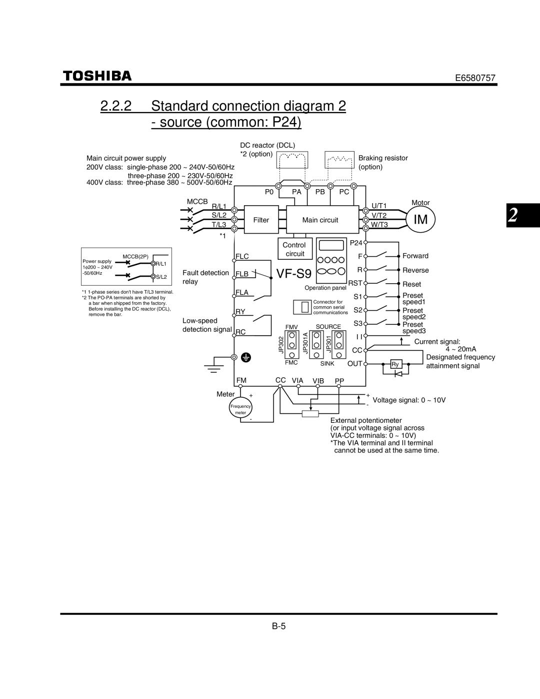
Standard connection diagram 2 source common P24
VF-S9
Power supply and motor connections
Description of terminals
Main circuit terminals
Connections with peripheral equipment
Control circuit terminals sink logic
Main circuit
Input Standard default setting 0~10Vdc input Internal imped
~60Hz60Hz setting frequency
Put. Standard default setting output cur 1mA full-scale dc
By jumper JP302 switching Full scale DC am
Multifunction programmable relay contact
= 1, 30Vdc-1A, 250Vac-1A cos φ = At resistance load
Output Detects the operation of the inverters 30Vdc-1A
During protection function operation
Input Common Output
Logic switching/voltage-current output switching jumper
Operations
How to operate the VF-S9
Wiring
Motor
Main circuit
E6580757
Mccb
Motor
Adjustment range
Simplified Operation of the VF-S9
Monitor display selection Is set to
How to start and stop
How to set the frequency
Setting the frequency using the operation panel
Example of operating a run from the panel
Moves the frequency down
Potentiometer
E6580757
Setting monitor mode Mode for setting inverter parameters
Status monitor mode Mode for monitoring all inverter status
Basic VF-S9 operations
VF-S9 has the following three monitor modes
How to set parameters
Setting monitor mode
How to set the basic parameters
Press the Enter key to save the changed maximum frequency
How to set extended parameters
Key and the key to select
Search and resetting of changed parameters
Example of parameter setting
Key to change the dynamic braking selection from
How to search and reprogram parameters
How to program setup parameters
Returning all parameters to standard default setting
Command mode selection Set , and and can
Parameters that cannot be changed while running
Key operated LED display Operation
Key or the key to change the set value. To return to
Pressing the Enter key displays
Setting acceleration/deceleration time
Basic parameters
Automatic acceleration/deceleration
Set automatic acceleration/deceleration to or
Manually setting acceleration/deceleration time
Parameter setting Title Function Adjustment range
Acceleration time Seconds
Deceleration time Seconds
Increasing starting torque
Automatic torque boost
Automatic torque boost and V/F control mode selection
Set V/F control mode selection to 0 V/F constant
If auto-tuning error Appears, see 6.13
Auto
Setting environmental protection
Setting parameters by operating method
Automatic environment setting
Automatic function setting
VIA/II UP/DOWN
Selection of operation mode
Command mode selection Frequency setting mode selection
Command mode selection
Title Function Adjustment range
Meter setting and adjustment
Preset-speed operation
Meter selection Meter adjustment
Adjustment scale with meter adjustment parameter
Resolution
Example of 4-20mA programmed output for details, see
Connect meters as shown below
Standard default setting
Adjusting the meter in inverter stop state
Default setting
Tion Is set to
Setting values
Parameter setting
Selecting forward and reverse runs operation panel only
Forward/reverse run selection
Maximum frequency
Upper limit and lower limit frequencies
Maximum frequency
Upper limit frequency Lower limit frequency
Base frequency
Base frequency
Base frequency 25 ∼ 400 Hz
Selecting control mode
Control mode selection
Time
Selection
Constant torque characteristics general method of use
Setting for fans and pumps
Setting V/F control selection Automatic torque boost
Increasing starting torque
Motor constant must be set
This gives steady torque for stable runs
Precautions on vector control
Energy-saving
Sorless vector control
Somewhat lower
Setting the electronic thermal
Manual torque boost increasing torque at low speeds
Torque boost
Title Function Adjustment range Default setting
Overload
Protection Stall
Motor electronic thermal pro
Setting of motor electronic thermal protection level
Default setting 100% Press Key to change the parameter to
Setting the motor electronic thermal protection level
Setting value Overload protection Overload stall
Preset-speed operation speeds in 15 steps
Inverter over load characteristics
Preset-speed operation frequencies 1~7
Preset-speed operation frequencies 8~15
Preset-speed
S3-CC
Terminal functions are as follows Terminal S1
=6 SS1
Using other speed commands with preset-speed command
Example of 7-step speed operation
Low-speed signal
Low-speed signal output frequency
Low-speed signal output frequency ∼ Hz
Extended parameters
Output of designated frequency reach signal
Parameter setting of output terminal selection
Speed reach detection band
Output of set frequency speed reach signal
Speed reach setting frequency Speed reach detection band
Parameter setting of set frequency and detection band
Title Function Adjustment range Setting
Input signal selection
Changing the standby signal function
ST standby signal selection
Setting the reset signal
Terminal function selection
Keeping an input terminal function always active on
Modifying input terminal functions
Always-active function selection
Setting of contact input terminal function
Terminal Title Function Adjustment range Default setting
Input terminal selection 3 RST Reset
Connection method Contact input Sink logic
Example of application ... Three-wire operation
Case of three-wire operation Set to
Sink logic/source logic input
Input terminal selection
Setting of output terminal function
Modifying output terminal functions
Examples of application
Output terminal selection
Switching motor characteristics via terminal input
Setting of switching terminals
Basic parameters
Automatic frequency switching
Frequency priority selection
External switching Fchg enabled
Set frequency is cleared automatically after power-off
External contact UP/DOWN
Contact input. See
Setting frequency command characteristics
10Vdc voltage input adjustment VIA, VIB
20mAdc current input adjustment
Sample sequence diagram 1 Adjustment with continuous signals
Adjustment with pulse signals Parameter-setting example
Sample sequence diagram 2 Adjustment with pulse signals
Frequency adjustment range
Minimum unit of frequency adjustment
Simultaneous input
Starting frequency setting
Operation frequency
Starting frequency
Function Frequency set with the parameter
2 Run/stop control with frequency setting signals
DC braking
DC braking
Jog run mode
Jog run frequency Jog run stopping pattern
DC braking time 20.0 sec
Jog run setting
Jump frequency jumping resonant frequencies
Jump frequency Jumping width Jump frequency 3 Jumping width
Preset-speed operation frequency 8 to
∼ Preset-speed operation frequency 8 to
Random mode
PWM carrier frequency
Trip-less intensification
Auto-restart Restart during coasting
Auto-restart control selection
Restarting motor during coasting Motor speed search function
DC braking during restart
Regenerative power ride-through control
Regenerative power ride-through control
If momentary power failure occurs
Application
Canceling conditions
Retry function
Retry selection
Dynamic regenerative braking
Dynamic braking selection Braking resistor operation rate
Connecting an external braking resistor optional
Parameter setting Title Function
Separate-type optional resistor with thermal fuse
Setting the braking resistor operation rate
12.5 Avoiding overvoltage tripping
Minimum resistances of connectable braking resistors
Overvoltage limit operation
Output voltage adjustment/Supply voltage correction
To the base frequency So that no
Output voltage unlimited
Conducting PI control
External connection
100.0 Integral gain
100.0
Setting PI control
Adjusting the PI control gain level
Gain adjustment parameter
Types of PI control interfaces
Adjusting analog command voltages
Setting motor constants
Selection 1 Setting by automatic torque boost
Set the auto-tuning parameter to
See .2 for details of the setting method
Rameters Auto-tuning Application of individual settings
Perform adjustments according to the actual operation
To the actual operation
Deceleration time 3600 s
Acceleration time 3600 s
Acceleration/deceleration patterns
Linear acceleration/deceleration
Switching to acceleration/deceleration
Selection using parameters
Setting motor electronic thermal protection
Protection functions
Setting current stall
Inverter trip retention
Stall prevention level
Inverter trip retention selection
External input trip stop mode selection
External trip stop via terminals
Is set to Emergency DC braking, also set
Emergency DC braking time
Output phase failure detection
Output phase failure detection mode selection
Failure detection signal generated FL relay deactivated
Emergency stopping from the operation panel
Input phase failure detection
Control mode for small current
Input phase failure detection mode selection
Specified time Title Function Adjustment range
Disabled Enabled Over-torque trip/alarm level ∼ 250 %
Over-torque trip
Level flows for more than
Detection signal
No trip Over-torque detection Pre-alarm signal
Output terminal function 12 OT Over-torque detection
No trip Over-torque
Undervoltage trip
15.10 4-20mA dc calibration
Undervoltage trip selection
Meter bias
Prohibition of change of parameter settings
Examples of setting
Prohibition of change of parameter settings
Setting methods
Resetting method
Changing the display unit to A/V/min-1
Unit selection
Free unit selection
Display in percentage terms Display in amperes/volts
Changing the display format while power is on
Standard monitor mode ⇒ Standard monitor display selection
Changing the status monitor display format
Standard monitor display selection
Communication function Common serial
Using the RS232C/RS485
Setting the communication functions
Transmission specifications
Communication function parameters Common serial options
Command by communicating independently
Example of connection for RS485-communication
Next data Use the terminal board to branch the cable
Number, to the host computer
Setting the operation frequency
Operation panel key setting
Applied operation
S1 UP S2 Down S3 CLR
Preset-speed setting
Switching between external contact UP/DOWN VIA input
To switch to VIA/II setting, use the external PNL/TB
S1FCHG
Switching between analog setting and preset-speed setting
Signal Voltage signal
Setting by means of a remote input device
Operation is controlled in accordance with Setting
Setting the operation mode
Terminal board operation
Case of three wire operation Set to
Enable to run at HD on
Eration holding S1 terminal set to
Operation, inverter stop
S2 PNL/TB VIA VIB
Operation from an external input device
OFF
LED
Display of trip information
Display of trip information
Example of call-up of trip information
E6580757
How to cope with the CE directive
Taking measures to satisfy the CE/UL directive
About the EMC directive
Measures to satisfy the EMC directive
Example of wiring
Single-phase 200V class
About the low-voltage directive
Measures to satisfy the low-voltage directive
Inverter satisfies the low-voltage directive
Plate. Refer to the .1 for earth cable sizes
Selection of wiring materials and devices
Peripheral devices
Selection of wiring devices
Installation of a magnetic contactor
Magnetic contactor in the primary circuit
Magnetic contactor in the secondary circuit
Installation of an overload relay
Optional external devices
Effect Reactor type Power factor Harmonics Suppression
200V-3.7kW Improvement Other model
Or less Input AC reactor DC reactor
Actor effective for external surge suppression
Ward/reverse switch Model CBVR-7B1
Parameter writer
Model PWU001Z Extension panel
UP/DOWN key, Monitor key, and Enter key Model RKP001Z
Devices
Input AC re Actor
DCL
Devices External dimensions and connections Foot Mounted
Noise filter
Devices External dimensions and connections Braking Resistor
Devices External dimensions and connections Parameter
Writer Exten
Sion panel
Communica
Table of parameters and data
User parameters
Four automatic functions
Other Basic parameters
Extended parameters
Input/output parameters
Frequency parameters
VIB, VIA/II
0213 VIB input point 400 Frequency Frequency Down
Operation mode parameters
Torque boost parameters
Acceleration/deceleration time parameters
Protection parameters
Operation panel parameters
Communication parameters
Default settings by inverter rating
Table of input terminal functions 1/3
Table of input terminal functions 2/3
ST+PNL/TB
Table of input terminal functions 3/3
Table of output terminal functions 1/2
Table of output terminal functions 2/2
POL
Order of precedence of combined functions
Specifications
Models and their standard specifications
Standard specifications
Specification
Outside dimensions and mass
Outside dimensions and mass
Fig.A
Plate
Before making a service call Trip information and remedies
Trip causes/warnings and remedies
Problem Possible causes Remedies Overvoltage during
Problem Possible causes Remedies Small-current opera
Process of initializa Values
Restoring the inverter from a trip
If the motor does not run while no trip message is displayed
How to determine the causes of other problems
How to cope with parameter setting-related problems
Inspection and maintenance
Regular inspection
Periodical inspection
Check points
Check items
Call the local sales agency
Replacement of expendable parts
Standard replacement cycles of principal parts
Making a call for servicing
Keeping the inverter in storage
Warranty
Disposal of the inverter
Toshiba Corporation