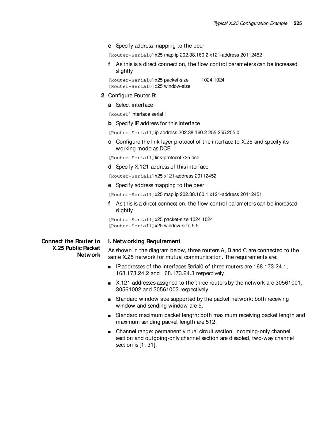
3Com Router Configuration Guide
Campus Drive
3Com Corporation
Marlborough, MA
01752-3064
Page
VPN
List conventions that are used throughout this guide
This guide describes 3Com routers and how to configure them
Text Conventions
About this Guide
3Com Router Introduction 3Com Router User Interface
Page
3COM Router Introduction
Following table lists the basic features of the 3Com Router
Features of the 3Com
List of the 3Com Router 1.x features
Router Version
RIP-1/RIP-2
NAT
Quality of service
3Com Router
New Features of the 3Com Router 1.x
3COM Router Introduction
Establish
Configuration
Environment
Port
Establish a new connection
Set port communication parameters
Establish a remote configuration environment
Connection
Configuration
Environment
Router
Workstation Ethernet
Interface CLI
Command Line
3COM Router User Interface
Views and their prompts
System view Table
Ethernet 0 in any
Async 0 in any
Loopback 0 in any
Enter controller
Full help
Helps
Partial help
Common error Message Causes
List of common command line error messages
For example
Routerdisplay ?
Features
Command Line
Display Features
Three options are available for users
Please perform the following commands in system view
Following commands
User Identity
Management
System
Configure the router name
Set the system clock
Execute the following commands in all views
By default, the system clock is 080000 1 1
Reboot the system
Display the System Information Router
System Management
Page
Softwaresoftware
Storage Media and File Types Supported by the System
Input Ctrl+D, and the following prompt information displays
Upgrade Boot ROM Software
Router Main Program
Upgrade the 3Com
Software
Main Program software
XModem Approach
Modify the terminal baud rate
Transfer File dialog box
Enable the Tftp server program
Preparation for using the Tftp server
Tftp server application can run on Windows 95/98/NT
Tftpd32 Set interface
Press Enter and the following prompts will be displayed
Network Interface Parameters
Enter Ctrl+B and the system prompts
Operation Command Downloads the 3Com Router main
Download configuration files from a Tftp server
Press Enter for loading
Get ip-addr file-name system
Set an authentication mode for an FTP server
Prepare for using the FTP server
Enable FTP server
Upgrade the 3Com Router Main Software with FTP
Tftp Approach
Back up the 3Com Router Main Program Software
FTP Approach
Copy ip-addr file-name system
Setup Users Dialog Box
Update slot slot-number ftpserver host-name
Configure on-line upgrading of the card
Port-number user user-name password
Password
Download Configuration File
Configuration File Management
Perform the following command in system view
Content and Format of the Configuration File
Download Config
Load configuration files
Router download config
Set the binary transmission protocol to XModem/CRC
Back up Configuration Files
Display current-configurationcommand output backup approach
Upload configuration files to a Tftp server
File-name config
View router configuration
Please use the following commands in corresponding views
Save current configuration
Select and view the storage media of configuration file
Set the Flag Bit to Enter the Initial Setup Mode
Erase the configuration file in storage media
Configure authentication and authorization of FTP server
Configure FTP
Client via port 20 and transfer data
Files on the router
Configure Parameters of FTP Service
Enter the following commands in system view
Please enter the following commands in system view
Set the authentication mode of FTP server
Set the connection time limit of FTP service
Set FTP update mode
Force to shut down FTP process
Force to shut down FTP process
Display ftp-server
Display FTP Server Display FTP server
Server Display detailed information of the FTP user
Display local-user
System Management
Features of Terminal
Terminal Service
Service at Console Port
Overview
Set the attributes of terminal service
Service
Terminal Message
On one router
Configure Terminal Message Service
Perform the following configuration in all views
Display Terminal Message Service
Enable/disable receiving messages from other terminals
Terminal Service
Typical Example Terminal Message Service Configuration
Dumb Terminal
Configure Dumb Terminal
Configuration Examples Dumb Terminal Service
Configure Auto-execute command
By default, no dumb terminal service is configured
Configure the interface to dumb terminal mode
Terminal Service Telnet Connection
Configure the auto-execute command command
Router-Serial1auto-execute command telnet
Service Value
Terminal service features of telnet connection
Establish Telnet Connection
Enable Reverse Telnet connection
Setup Reverse Telnet Connection
Service-port
Establish Telnet Server or Telnet Client connection
Force shut down Telnet Process
Typical Configuration Example of Telnet Reverse Telnet
Example of Telnet
Force to shut down Telnet process
Use Rlogin protocol
Rlogin Terminal
Example of Reverse Telnet
Router telnet 10.110.164.44
Typical Rlogin Configuration Examples
Establish a Rlogin connection
Rlogin ip-address username
Use local user name abc to log on
PAD Remote
Access Service
Communicate with other terminals through the X.25 network
Configure X.25 PAD remote user
Configure X.25 PAD remote user
Service-type type password
Local-user user-name
Enable AAA authentication for X.25 remote PAD users
Start AAA authentication of X.25 remote users
Establish an X.25 PAD call
Establish a X.25 PAD call
III. Configuration Procedure
II. Networking Diagram
Display and Debug
Set the Response Time to the Invite Clear Message
Set its X.121 address as
Fault Diagnosis Troubleshooting
RouterA-serial0x25 x121-address
RouterB-serial0x25 x121-address
Development of Snmp
Snmp Overview
Configuring Network Management
SNMP-supported MIB
Snmp architecture
3Com Router-supported MIB
By default, the system disables Snmp service
Engineid
Configure Snmp version and related tasks
Perform the following configurations in system view
Configure the traps to be sent by the router
Configure information of router administrator
V1 username
Interface-number
Display and debug Snmp
Perform the following commands in all views
Name
Byte-count
Set the community name and access authority
Example 1 Configure Network Management of SNMPv1
Configure an IP address for the Ethernet interface ethernet
Examples Networking Requirements
Rmon Overview
Configure an IP address for the Ethernet interface ethernet
Network equipment
Schematic diagram of Rmon application
Examples Networking Requirement
Enable Rmon statistics
RouterA-Ethernet0 rmon promiscuous
Commands to display information of the whole system
Test Tool of Network Connection
Ping command
System displays
Ping supporting IP protocol
Ping supporting IPX protocol
Ip-address
Tracert command
Following command can be executed in any command modes
Timeout host
MaxTTL -p port -q nqueries
Log Function
Configure on the router
Set the direction of syslog outputting log information
Perform the following task in system view
Set Severity of Log Information
Sylog-defined severity is as follows
Set Filter of Log Information
Turn on/turn off syslog
Configuration of Log Host
Display and Debug Syslog
Turn on/turn off syslog
Turn on debugging switch of PPP module
Syslog Configuration Example
Routerinfo-center enable
Routerdebug ppp all
Display and Debugging Tools
Dial-up POS Access
POS Terminal Access Service
Advantages of POS network access are as follows
POS Network Access
Configure POS access port
POS Access Service Configuration
Start POS server
Interface-type interface-number
Configure a POS application
App-number
Ip-address port-number
Default app-number
Configure POS multi-application mapping table
Bind the source address of TCP connection
Display and debug POS access
Display and Debug POS Access
Set the parameters of FCM used during Modem negotiation
Set the parameters of FCM used during Modem negotiation
Configure the Ethernet interface Ethernet
Typical Configuration Example of POS Access Service
Configure the POS access interface FCM0
Configure POS access interface FCM1
Configure POS access interface FCM0
Configure POS access interface FCM2
III. Configuration Procedure 1 Start the POS access server
Configure Async 1 to operate in POS application mode
Configure Async 0 to operate in POS application mode
III. Configuration Procedures
Configure Router a Start the POS access server
RouterA ip route-static 10.1.1.2 255.255.255.0 serial
Configure Router B Configure the Ethernet interface Ethernet
III Interface
106
Interface
Configure Interface
Enter the Interface View
Interface view, input quit to return to the system view
Exit the Interface View
Set time interval for flow control statistics
Interface-description
Display and Debug Interface
Please use the following commands in all views
Display and debug interface
Interface state information
Interface Configuration Overview
Ethernet Interface
Configure Ethernet Interface
Set IP address
Enter view of specified Ethernet interface
Set IPX address
Set frame format of sending message
Enable or disable internal loopback and external loopback
Select work mode of Ethernet interface
Display and Debug
Select working rate of fast Ethernet interface
Troubleshooting
Typical Ethernet Interface Configuration Example
II. Network Diagram
Troubleshooting
Configuring LAN Interface
Introduction
WAN Interface
Asynchronous Serial Interface
Interface async number
Enter view of specified asynchronous interface
Interface serial number
Set the baud rate of asynchronous serial interface
Set the work mode of asynchronous serial interface
Modem in out
Link-protocol slip ppp
Flow-control none software
Async Mode protocol
Hardware inbound outbound
Parity even mark none
Works in flow mode
Odd space
Stopbits 1 1.5
AUX Interface
Backup
Set MTU of asynchronous serial interface
Set the coding format of Modem
Configure AUX interface
Configure AUX interface
Configure Synchronous Serial Interface
Synchronous Serial Interface
Set the link layer protocol of synchronous serial interface
Enter view of specified synchronous interface
Physical-mode sync
Link-protocol fr hdlc
Working modes have different working clocks
Select work clock
Set the baud rate of synchronous serial interface
Synchronous serial interface is 64000 bps
Select work clock
Inversion is disabled by default
Set clock inversion
Detect dcd
Internal loopback/external loopback are disabled by default
Undo detect dcd
Reverse-rts
Idle coding of synchronous serial interface is 7E
Isdn BRI Interface
Technical Background
Graphics and video
Be clear about the following items before the configuration
Preparations before Configuration
Function group includes
CE1/PRI Interface
Channelized operating mode
Network protocols such as IP and IPX
Interface or a PRI interface
Dial-on-Demand Routing
Configure CE1/PRI CE1/PRI interface configuration includes
Interface
Enter the view for a specified interface
Bind the interface to be channel sets
Enter the synchronous serial interface view
Number set-number
Enter the Isdn interface view
Bind the interface to be a pri set
Pri-set timeslot-list range
Undo pri-set
Set the line code format on the CE1/PRI interface
Enable/disable the internal loopback/external loopback
Set the line clock of the CE1/PRI interface
Set the frame format of CE1/PRI interface
CT1/PRI Interface
Configure CT1/PRI
Controller t1 number
Operation Command Enter the view of CT1/PRI interface
Timeslot-list range speed
Interface serial number23
Set the line clock of the CT1/PRI interface
Set the line code format on the CT1/PRI interface
Set the frame format of CT1/PRI interface
E1-F interface does not support PRI operating mode
Choice for E1 access
E1-F Interface
Them into multiple channel sets
Enter the view of an E1-F interface
Set Operating mode for an E1-F interface
Interface serial serial-number
Fe1 unframed
Set line code format for E1-F interfaces
Set interface rate after binding operation
Set line clock for an E1-F interface
Set frame format for an E1-F interface
Enable/Disable local/remote loopback on an E1-F interface
Display and debug E1-F interface
Serial-number
T1-F interface does not support PRI operating mode
Choice for T1 access
T1-F Interface
193 X 8k = 1544kbps
Set line code format for T1-F interface
Set line clock for a T1-F interface
Enable/Disable local/remote loopback on a T1-F interface
Set frame format of T1-F interface
CE3 Interface
Other related information
Display and Debug T1-F
Display and debug T1-F interface
Enter the view of the specified E3 interface
Set the operating mode of E1 channel
Set the operating mode of CE3 interface
Set E1 frame format
CT3 Interface
Mode non-channelized mode
44.736Mbps
Data bandwidth 44736kbps
Set clock mode of the T1 channel
Set clock mode of the CT3 interface
Enter specified CT3 interface view
Set cable length of the CT3 interface
By default, the CT3 interface uses the C-bit frame format
By default, loopback is disabled Set Frame Format
Perform the following configurations in CT3 interface view
Set CRC of the serial interface
Set the operating mode of T1 channel
T1 line-number unframed
Display and debug of the CT3 interface
Disable and Enable CT3 interface
Configuring WAN Interface
Dialer Interface
Logical Interface
Null Interface
Configure Loopback
Sub-Interface
Create and delete WAN sub-interface
Configure sub-interfaces of Ethernet interface
Number.sub-number
Number.sub-number multipoint
Select frame relay link layer protocol
Enter the view of WAN interface Serial0 of router a
Routerinterface serial
Specify DTE as its frame relay terminal type
Configure the static route from router a to LAN2 and LAN3
Set its IP address to 202.38.160.1 and address mask to
Allocate a virtual circuit with Dlci 50 to it
Create or delete virtual-template
Set work parameters of virtual-template
Interface virtual-template
Undo interface
Troubleshooting the reasons may be as follows
Fault 1 Fail to create virtual interface
Display state of the specified virtual-template
Virtual-template-number
Link Layer Protocol
164
PPP Overview
PPP Authentication Mode
Configuring PPP and MP
MP Overview
Configure PPP
For detailed description of PPP, refer to RFC1661
Transmission time of large packets
Configure the local authenticates the peer in PAP mode
Configure the link layer protocol of the interface to PPP
Configure the peer authenticates the local in PAP mode
Name-list
Configure as the peer authenticates the local in Chap mode
Configure the local authenticates the peer in Chap mode
Cipher password
User username
Configure the time interval of PPP negotiation timeout
Configure AAA authentication and accounting of PPP
Configure PPP compression
Configure PPP link quality monitoring
Perform the following configuration in interface view
Ppp lqc forbidden-percentage
Resumptive-percentage
Configure Operating Parameters of Virtual Template
Configure MP Protocol Parameters Create Virtual Template
Create/Delete virtual template
Bind the physical Interface to a Virtual Template
User-name
Specify the conditions for MP binding
Frags
Configure virtual Baud rate on interface
Configuration Requirement
Typical PPP Configuration Example
Example
II. Configuration Procedure
Typical MP Configuration Example
Configure to start Chap authentication at this side
Set local username as Router1
Configure router-b Add a user for router-a
Configure virtual interface template
Configure router-c Add a user for router-a
Fault 1 Link always fails to turn to up status
Fault Diagnosis Troubleshooting
Fault 2 Physical link fails to turn to Up status
Indicates that the interface is shutdown
Introduction to PPPoE client
PPoE Overview
Client
Configure PPPoE
Reset or delete PPPoE session
Configure PPPoE session
Perform the display and debugging command in all views
Typical PPPoE Configuration Example
Access a LAN to the Internet via Adsl
III. Configuration Procedure 1 Configure a dialer interface
Configure the LAN interface and the default route
Configure a PPPoE session
Configure the DDN interface Serial
Use Adsl as Standby Line
Configuring Pppoe Client
Asynchronous mode
Configure Slip
Slip Overview
For further details about SLIP, you can refer to RFC1055
Typical Slip
Enable/Disable the information debugging of Slip
Time
Interconnect two Router routers via Pstn and run IP
Configure IP address of synchronous/asynchronous interface
Configure Router a Configure Dialer Rule
Configure the Dialer String to router B
Configure the default route to Route B
Routerip route-static 0.0.0.0 0.0.0.0
Isdn Overview
Configure Isdn
Configure type of signaling on Isdn interface
By default, DSS1 signaling is used on Isdn PRI interfaces
Configure the length of call reference
Configure the receiving mode
Configure interval for Qsig signaling timer
Configure the sending mode
Timer-name all
Time-interval
Perform the following configuration in Isdn interface view
Configure Call Processing Method on an Interface
Perform the display and debugging commands in all views
Configure Router a Create an Isdn PRI interface
Typical Configuration Example
Configure the Isdn PRI interface
RouterB transmit data after the call is set up
Configure Router B
Configure Router a
Protocols Overview
Lapb
PSN
25 packet and Lapb frame
By default, the Lapb modulus is Modulo
Configure Lapb
By default, k is Configure Lapb N1, N2
Configure
Set/Cancel the X.121 address of the interface
Configure X.25 Interface
Set X.25 working mode
Address
Parameter Meaning
25 channel delimitation parameters
Set/cancel X.25 virtual circuit range
By default, X.25 interface use modulo 8 mode
Set/Cancel X.25 packet numbering modulo
Finally, the following should be noted
Configure X.25 Interface Supplementary Parameter
Configure X.25 flow control parameter
Set the default flow control parameter
Out-packets
Set X.25 layer 3 timer delay
25 layer 3 timer
Alias match modes and meanings
Specify/Cancel an alias for the interface
Alias-string
Match-type alias-string
Set/Cancel the default upper layer protocol borne on
Create the permanent virtual circuit PVC
Configure X.25 Datagram Transmission
Protocol-address x121-address
Address option
Create/Delete permanent virtual circuit
Configure Additional Parameters Datagram Transmission
X25 pvc pvc-number protocol
Undo x25 pvc pvc-number
Interface view, perform the following task
Configure X.25 user facility
Specify/Cancel packet pre-acknowledgement
Serial port view, list1 can be quoted
Configure the sending queue length of virtual circuit
Set interface with standby center
Set broadcast via
Address broadcast
Address logic-channel
Configure X.25 sub-Interface
Switching Function
Configure X.25 Switching
Number.subinterface-number multipoi
Add or delete a PVC route
Configure X.25 Load Balancing
Introduction to X.25 Load Balancing
Configure X.25
Diagram of X.25 network load balancing
List of Configuration Tasks of X.25 Load Balancing
Create/Delete X.25 hunt group
Start /Close X.25 switching function
Add/Delete interfaces or XOT Tunnels in hunt group
Add/delete other X.25 switching routes
Configure X.25 over Other Protocols
Configure X.25 over TCP XOT
Introduction to XOT Protocol
Configure XOT
Configure local switching
Start X.25 switching
Configure SVC XOT switching
For PVC, perform the following tasks in interface view
Configure PVC XOT switching
Configure Annex G Data Interoperation
Configure X.25 over Frame Relay Annex G
Configure Keepalive and xot-source attributes
Configure the X.25 attributes for an Annex G Dlci
Configure the X.25 Attributes for a Dlci
By default, X.25 template is not applied on DLCIs
Typical Lapb Configuration Example
Current status of Lapb
Specify IP address for this interface
Configure Router a a Select interface
Configure Router B Select interface
Specify X.121 address of this interface
Connect the Router to X.25 Public Packet Network
Specify address mapping to the peer
Configure Router B Configure interface IP address
Configure Router a Configure interface IP address
Configure Router C Configure interface IP address
Disabled
Configure Virtual Circuit I. Networking Requirement
Range
Transmit IP Datagram via X.25 PVC
Router-Ethernet0ip address 196.25.231.1
Typical Sub-Interface Configuration Example
Configure Router D
Configure Router C
Create sub-interface serial
SVC Application of XOT I. Networking Requirement
Configure Serial
Configure Router C Start X.25 switching
Routerx25 switch svc 2 interface serial
Routerx25 switch svc 1 xot
Application of X.25 Load Balancing
Configure X.25 switching route to forward to X.25 terminal
Enable X.25 switching in system view
S11
Add Serial 1, Serial 2 and XOT Tunnel to hunt group
Routerx25 switch svc 8888 interface serial
Routerx25 switch svc 1111 xot
Load Balancing Carrying IP Data Transmission
Routerinterface serial Router-Serial0link-protocol x25 dce
Configure interface Serial
Configure RouterA Configure interface Ethernet
Configure static route to RouterC
Configure RouterB Configure interface Ethernet
Configure RouterA Create an X.25 template
Configure the static route to RouterA and RouterB
Configure the local X.25 address
Configure an IP address for the local interface
Map the Frame Relay address to the destination IP address
Configure RouterB Create an X.25 template
Associates an X.25 template with the Dlci
SVC Application of X.25 over Frame Relay
Enable switching on Frame Relay DCE
Configure the router Router B Enable X.25 switching
Configure Serial 0 as the X.25 interface
Configure Serial 1 as the Frame Relay interface
Configure the router Router C Enable X.25 switching
Configure X.25 over Frame Relay switching
Configure the Frame Relay Annex G Dlci
Configure local X.25 switching.Router-fr-dlci-100annexg dte
Configure Router B Enable X.25 switching
Configure Router D Configure the basic X.25 parameters
Configure an X.25 template
Configure S1 as the Frame Relay interface
Lapb
Configure Serial Configure S1 as the Frame Relay interface
Facility options inhibited by network have been carried
Fault Diagnosis and Troubleshooting of X.25
Configuring Lapb
Configuring Frame Relay
Link-protocol fr ietf
By default, the interfaces link layer protocol is PPP
Relay
Nonstandard
Configure Frame Relay LMI protocol type
Configure Frame Relay interface type
Undo fr lmi-n391dte
Fr lmi n391dte n391-value
Fr lmi n392dce n392-value
Undo fr lmi n392dce
Fr lmi t391dte t391-value
Undo fr lmi n393dce
Undo fr lmi t391dte
Fr lmi t392dce t392-value
Configure Frame Relay dynamic address mapping
Configure Frame Relay static address mapping
Create Frame Relay sub-interface
Configure Frame Relay local virtual circuit number
Fr dlci
Undo fr
Applying dynamic address mapping to the sub-interface
Configure virtual circuit of Frame Relay sub-interface
Establish static address mapping
Configure the route for Frame Relay PVC switching
Configure the Frame Relay local virtual circuit number
Configure Frame Relay local switched PVC number
Configure the Frame Relay switched PVC
Overview
Configure Multilink Frame Relay FRF.16
Configure a MFR bundle interface MFR interface
Configure MFR
Configure MFR interface parameter
Subnumber
Configure the parameters of the bundle link interface
Frame Relay Compression Configuration
Configure Frame Relay Fragment FRF.12
By default, interfaces use initiative compression
Configure Frame Relay Fragment Attributes
Configure Frame Relay Compression on multipoint interface
Frame Relay Traffic Shaping
Disable the Frame Relay traffic shaping
Fr traffic-shaping
Undo Fr traffic-shaping
Rate
Frame Relay Traffic Policing
Frame Relay Queueing Management
100 Kbps CI R ALLOWº£ 64 Kbps
150 Kbps
Frame Relay DE rule list
Frame Relay Congestion Management
Configure the Frame Relay class parameters
By default, no Frame Relay class is created
Configure Frame Relay Traffic Shaping
Undo fr-class class-name
Configure the parameters of Frame Relay class
Enable/Disable the Frame Relay traffic shaping
Enable/Disable the Frame Relay traffic policing
Dequeue-percentage
Queue-percentage
Configure Frame Relay Queueing Management
Configure Frame Relay DE Rule List
Configure the Frame Relay PVC queueing
Configure Pipq
Configure Frame Relay over IP
Configure Frame Relay over Other Protocols
Configure a tunnel interface
Configure Frame Relay switching
Networking of a typical Frame Relay over Isdn application
Frame Relay over Isdn Operation Process and Fundamentals
Physical Connection Between Frame Relay over Isdn Devices
Frame Relay switching connection between DTE devices
Back-to-back connection between DTE and DCE devices
Configure the Frame Relay-related commands
Configure Frame Relay over Isdn
Configure the link layer protocol of the interface
Configure the commands related to Frame Relay switching
Dlci
Display and debug Frame Relay
Configure parameters related to dialer profiles
Display and Debug Frame Relay
Isdnsubaddress
Number interface serial
Number dlci dlci-number
Type number dlci
Mfr number
Configure static address mapping
Typical Frame Relay Configuration Example
Interconnect LANs via Frame Relay Network
Router-Serial1fr map ip 202.38.163.251 dlci
Relay FRF.16
Configure local virtual circuit
Interconnect LANs via Private Line
Router-Serial1ip address 202.38.163.253
Bundle Serial 0 and Serial 1 to mfr
Create a MFR interface
Example FRF.9
Them
III. Configuration Procedure 1 Configure RouterA
III. Configuration Procedure 1 Configure Router a
FRF.12
Fragment between them
Routerfr class 96k
IP Configuration
Router-fr-class-96ktraffic-shaping adaptation becn
Typical Frame Relay over
Configure tunnel interface
Configure IP interface Ethernet0
Configure Frame Relay over IP
Router-Serial0fr interface-type dce
Router-Bri0fr map ip 110.0.0.2 dlci
Configure the Frame Relay parameters on Bri0
Router-Dialer0dialer number Router-Dialer0dialer call-in
Router-Dialer0fr interface-type dce
Configure the Frame Relay-related parameters on Bri0
Router-Serial1.1ip address 130.0.0.2
Configure Frame Relay SVCs
Fault 1 the physical layer in Down status
Fault Diagnosis Troubleshooting Frame Relay
Fault 4 Frame Relay data cannot be transmitted across Isdn
Configuring Frame Relay
Configure Hdlc Display and Debug Hdlc
Configure Hdlc
By default, the link layer protocol of the interface is PPP
Configure the link layer protocol of the interface to Hdlc
Debugging Hdlc Packet Interface
Enable Hdlc packet debugging
Typical Bridge Configuration
Configure Bridge’s Routing Function
Bridge Overview
Bridge Overview
Main Functions of Bridging
Obtain address table
Bridge Overview
Final bridging address table
Forward and Filter
Filter not forward
Eliminating loop
Preliminary examination state of bridging loops
Spanning Tree Topology
Spanning tree topology
Bpdu Forwarding Mechanism
By default, disable bridging functions
Configure Bridge’s Routing Function
Enable/Disable bridging functions
Bridge enable
Specify the STP version supported by the bridge-set
Configure static address table entries
Add ports to a bridge-set
Mac-address
Configure the aging time of dynamic address table
Enable/Disable forwarding by using dynamic address table
Disable/Enable STP on ports
Configure the path cost of bridge port
Configure the bridge priority
Configure the bridge port priority
Configure the forward delay for the port status transition
Configure the interval for sending BPDUs
Create ACLs based on varied Ethernet encapsulation formats
Configure the Max age of Bpdu
Acl acl-number
Configure a bridge-template interface
Enable/Disable bridge’s routing
Bridge-set
Share load by source MAC address
Define a link-set
Link-set
Bridgebridge-set link-set link-set
Map the bridge address to Dlci
Configuration on the interface
Define a dialer list
Display and Debug Bridge
Typical Bridge Configuration
Display and debug bridge
Transparent Bridging Multiple LANs
Configure Router B
Configure Router a
Router-Serial0bridge-set 1 stp disable
Transparent bridge over the Frame Relay
Transparent Bridging over Frame Relay
Router-Serial1dialer route bridge broadcast
Standby
Asynchronous Dial-in
Connected are failed
Please refer to Figure
Networking of bridge-template interface
Bridge-Template interface
Networking for bridging on sub-interfaces
Bridging on Sub-Interfaces
Routerbridge enable Routerbridge 1 stp ieee
Link-Set Configuration I. Networking Requirements
Router-Serial1bridge-set 1 link-set
Network Protocol
316
Configuring IP Address
Network IP network range Description Class
IP address classes and ranges
Sub-net classification of IP address
By default, the interface has no master IP address
Configure IP Address Configure IP Address for an Interface
Configure master IP address of an interface
Ip address ip-address mask
Ip address ip-address mask Mask-length sub
Configure slave IP address of an interface
Delete slave IP address of an interface
Undo ip address ip-address
Configure IP Address Unnumbered for an Interface
By default, the interface has no negotiating IP address
Introduction to IP address unnumbered
Set negotiable attribute of IP address for an interface
Configure routing to Ethernet segment of Shenzhen router R1
Configuration Example I. Configuration Requirements
Configure IP address unnumbered
Borrow IP address of Ethernet interface
Borrow IP address of Ethernet
Configure router R1 of Shenzhen subsidiary
Router-Ethernet0ip address 172.16.20.1
Router ip route-static 0.0.0.0 0.0.0.0
Page
Configuring IP Address
Arp static ip-address
Define a static ARP mapping
Undo arp static ip-address
Arp dynamic ip-address
Name Resolution
Configure Domain
Name Resolution
Display and Debug ARP
Display and Debug domain name resolution
Display and Debug Domain Name Resolution
Display ip host
Specify the Vlan on which Ethernet subinterface is located
Create Ethernet subinterface
Interface-number.subinterface-number
Vlan-type dot1q vid vlan-id
Typical Vlan Configuration Example
Configure IP address of Ethernet subinterface
Display and Debug Display and Debug Vlan
Display vlan
Configure Vlan information of LAN Switch
Configure IP address for the subinterface
Troubleshooting The steps below can be taken
Router-Ethernet0.1ip address 3.3.3.8
Fault Ping Two PCs, but fails to ping them through
Dhcp Server Configuration
Dhcp vs Bootp
Background of the Dhcp development
Following figure
Occasions in which Dhcp server is applied
Dhcp server Dhcp clients
Dhcp client logs into the network again
Dhcp Server Configuration
Dhcp Enable
Enable/disable the Dhcp service
Undo Dhcp enable
Dhcp server ip-pool pool-name
Netmask
Configure the statically binding IP address and MAC address
Network ip-address
Low-ipaddress high -ipaddress
Low-ipaddress high-ipaddress
Configure the gateway router address of client
By default, the IP address of DNS is not configured
Configure the domain names of Dhcp clients
Configure the DNS addresses in a Dhcp address pool
Set the type of NetBIOS node for Dhcp client
Set the type of NetBIOS node for Dhcp client
Nbns-list ip-address1
Ip-address2 ... ip-address8
Configure Dhcp self-defined options
Use reset, debugging and display command in All views
Display and Debug Dhcp Server
Display and Debug Dhcp servers
Router dhcp enable
III. Configuration Procedures 1 Enable the Dhcp service
Router dhcp server forbidden-ip
Router-dhcp2nbns-list Router-dhcp2gateway-list
At the client, use ipconfig /releaseall
Operation Command Configure interface relay address
Configure interface relay address
Ip relay-address ip-address
Delete interface relay address
Dhcp Relay
Dhcp Relay Configuration Requirement
IP address from Dhcp server through application
Available on Dhcp server
Networking diagram of an Dhcp relay configuration example
Configure Dhcp relay router
Fault 2 fail to forward transparent transmission protocol
Under which condition should the address be translated
Private Network Address and Public Network Address
Role the Network Address Translation NAT plays
Characteristic of Network Address Translation NAT
Mechanism of Network Address Translation NAT
Performance of Network Address Translation NAT
Configure address pool
End-addr pool-name
Pool-name
Address-group pool-name
Nat outbound acl-number
Undo nat outbound acl-number
Undo nat outbound
Configure the Timeout of address translation
Configure the Internal Server
Nat server global global-addr global-port
Www inside inside-addr inside-port any
Display and Debug NAT Display and debug NAT
Typical NAT Configuration Example
Allow address translation of segment at 10.110.10.0/24
Configure address pool and access list
Set internal FTP server
Set internal WWW server
Configure dial-up property for the interface
Configure address access control list and dialer-list
Configure a default route to serial
Correlate the address translation list and the interface
Fault 2 Internal server abnormal
Configuring IP Application
To configure IP performance, carry out the following steps
Configure IP
Configure maximum transmission unit on an interface
Performance
Configure TCP
Tcp window size
Forwarding
Configure Fast
Display and Debug IP
Perform the following configuration in system view
Forwarding
Display and Debug Fast Display and Debug fast forwarding
Router info-center enable Router debugging tcp packet
Troubleshooting IP Performance Configuration
Router info-center enable Router debugging tcp event
Configuring IP Count
Enable/Disable IP Count service
IP Count Configuration
Ip count enable
Undo ip count enable
Configure IP Count list
Configure IP Count on an interface
Specify count maximum of exterior
Count
By default, IP Count entries time out after 720 minutes
Specify count maximum of interior
Display and debug IP Count
Not been configured on the interface of the router
IV. Test Procedure
Information is displayed
Configuring IP Count
IPX address
Configuring IPX
SAP
Modify length of service information reserve queue
Configure IPX
Configure relative parameters of IPX SAP
Its first Ethernet interface as its node address
Configure IPX RIP static route
Enable IPX interface
Enable/Disable a Default Route
Perform the following task in interface view
Configure RIP aging period
Configure RIP updating period
Configure the maximum size of RIP update packet
Configure the maximum number of IPX parallel route
Configure static service information table item
Configure length of route reserve queue
Configure size of SAP maximum updated message
Configure SAP aging period
Configure reply to SAP GNS request
Ipx sap timer update seconds
Disable split-horizon
Configure Using touch-off for an interface
Configure management of IPX packet
Configure the delay of interface sending IPX packets
Modify Encapsulation Format of IPX Frame on Interface
Encapsulation format of IPX frame
Display and Debug IPX Display and Debug IPX
Configure Router a a Activate IPX
Configure a static route to network ID
Configure an address map to Router B
Configure an information about Server2 file service
Configure an information about Server2 directory service
Configure an information about Server1 directory service
DLSw Protocol
Create DLSw local peer entity
Configuration of DLSw
Init-window-size max-frame
Max-frame-size max-window
Create DLSw remote end peer entity
Configure Bridge set connecting to DLSw
Configure Sdlc role
Configure to add ethernet port to Bridge set
Configure Sdlc address
Configure Sdlc virtual MAC address
Sdlc-address
Controller sdlc-address
Configure XID of Sdlc
Configure Sdlc peer entity
Add synchronous Interface to Bridge set
Configure baud rate of synchronous Interface
Configure to stop running DLSw
Baudrate
Configure parameters of DLSw timer
Configure Idle time encoding mode of synchronous Interface
Configure LLC2 local acknowledgement delay time
Mseconds
Configure modulo value of LLC2
Configure LLC2 premature acknowledgement window
Configure LLC2 local acknowledgement time
Configure retransmission number of LLC2
Configure Busy status time of LLC2
Configure P/F wait time of LLC2
Configure queue length of sending message of LLC2
Configure REJ status time of LLC2
Configure Queue Length of Sending Message of Sdlc
Configure Sdlc local acknowledgement window
Configure retransmission number of Sdlc
Configure maximum receivable frame length of Sdlc
Configure poll time interval of Sdlc
Configure data bi-directional transmission mode of Sdlc
Configure SAP address for transforming Sdlc to LLC2
Lsap
Dsap
DLSw Configuration Networking Requirement
Typical DLSw Configuration Example
DLSw
IP across WAN
Router B Configuration
Router a Configuration
DLSw Configuration
Router dlsw local
Networking diagram of DLSw configuration of SDLC-SDLC
Networking Diagram of SDLC-LAN
When using command display dlsw remote
DLSw Fault
Diagnosis
Virtual circuit cant attain Connected state
Diagnosis and Troubleshooting of DLSw Fault
Configuring Dlsw
VI Routing
404
IP Routing Protocol
IP Routing Protocol
Routing Protocol or Type Corresponding Routing Priority
Routing Protocol and Routing Priority
Ospf ASE
Default Route
Configuring Static Routes
Configuring a Static Route
Configuring a Static Route
Configure a Static Route
Transmitting interface or next hop address
Displaying Debugging Routing Table
Configuring a Default Route
Preference
Other parameters
Static Route
Troubleshooting a
Other
RIP Overview
Features is not subject to whether RIP has been enabled
Configure RIP
Enabling RIP
Enable RIP at the Specified Network
Define a Neighboring Router
By default, the interface runs RIP-1
Specify RIP Version
Peer ip-address
Configure Check Zero Field of RIP Version
RIP Version 1 enables zero field check by default
Disable a Host Route
Specify the Status of an Interface
Enabling Route
Authentication on
Summarization for RIP
Version
Configure RIP Horizontal Segmentation on the Interface
By default, the default route metric for RIP is
Configure Route Import for RIP
Specify a Default Route Metric Value for RIP
Distribution for RIP
Configure filtering route information received by RIP
Specify Additional Route Metric Value for RIP
Set Route Preference
Displaying and Debugging RIP
Reset RIP
Filter the Routing Information Being Advertised by RIP
Display and Debug RIP
RIP Unicast
Ospf Overview
Ospf Configuration Example
Ospf Overview
Displaying and Debugging Ospf
Configuring Ospf
Specify Router ID
Enable Ospf
Router id router-id
Undo router id
Area-id
By default, Ospf is disabled
Area area-id
Configure Sending Packet Cost
Configure the Network Type of the Ospf Interface
Ospf network-type broadcast nbma
P2mp P2p
Cost
Configuring a Peer for the Nbma Interface
Specify the Router Priority
Operation Command Set the priority of the interface when
Ospf Dr-priority value
Undo Ospf dr-priority
Specify Dead Interval
Specify Hello Intervall
Specify Transmit-delay
Configuring a Stubby Area and a Totally
Specify Retransmitting Interval
Configure Totally Stubby Area of Ospf
Perform the following configuration under Ospf view
Stub cost cost area area-id
No-summary
Configure an Nssa Area of Ospf
Perform the following configuration in Ospf view
Abr-summary address mask mask area
Configure Route Summarization Within Ospf Domain
Area-id advertise notadvertise
Undo abr-summary address mask mask
Area-id None Router-id None
Create and Configuring a Virtual Link
Key-id
Configure Authentication
Configure Parameters When Importing External Routes
Configure Route Import for Ospf
Displaying
Configure filtering route information received by Ospf
Debugging Ospf
Filter for Ospf
Configuring Ospf on the Point-to-Multipoint Network
Ospf Configuration Example
Router D 201 Router B 301 302 Router C 1.3
RouterC ospf enable
Enable Ospf
RouterA-Serial0ospf network-type p2mp
RouterB-Serial0ospf network-type p2mp
Configure DR on Ospf Preference
E0 192.1.1.4/24
1.1 4.4 E0 192.1.1.1/24
E0 192.1.1.2/24 E0 10.1.2.3/24
2.2 3.3
RouterD display ospf peer
RouterA display ospf peer
Between Router B and Router C
To configure an Ospf virtual link Configure Router a
RouterB-ospfVlink peer-id 3.3.3.3 transit-area
To configure Ospf peer authentication Configure Router a
Ospf Configuration
Troubleshooting an
Normally
Ospf Configuration Example
Configuring Ospf
BGP Overview
BGP Configuration Example
BGP Overview
Displaying and Debugging BGP
Configuring BGP
Perform the following configurations in system view
Resetting BGP Connections Enabling BGP
By default, BGP is disabled
Perform the following configurations in BGP view
Set the Timers for BGP Peer
Configure the BGP Version of the Peer
Configure BGP Route-update Interval
Configure to Send Community Attribute to the Peer
Configure to distribute default route to the peer
Configure the Peer to be the Client of the Route Reflector
Configure to Distribute Default Router to the Peer
Configure the BGP MED Metric
Create a Fltering Policy Based on Access List for the Peer
Create a BGP Route Filtering Based on AS Path for the Peer
Allow Comparing Path MED
Configure the Keepalive Timer and Holdtime Tmer for BGP
Configure the Local Preference
Timers keepalive-interval
Holdtime-interval
Add a Peer to the BGP Peer Group
By default, there is no BGP peer in a peer group
Peer group-name
Group-name
Configure Connection Between Peers Indirectly Connected
Configure AS Number of BGP Peer Group
Set the Timers of BGP Peer Group
Configure BGP Routing Update Sending Interval
Configure to Send the Default Route to the Peer Group
Configure to send the default route to the peer group
Create Routing Policy for Peer Group
Configure BGP Version of Peer Group
By default, software accepts BGP Version
Create an Aggregate Addresses
Aggregate address mask
By default, an aggregate is disabled
As-set
Undo aggregate address
Clients within the reflection group
Reflect between-clients
Undo reflect between-clients
Configure BGP Community
Configure the Cluster ID
Standard-community-list-number
Extended-community-list-number
Configure the Sub-system of E Confederation
Configure a Confederation
As-number …
Schematic diagram of route dampening
Display Route Flap Information
Is insured When AS is not a transitional AS Configuring
By default, BGP synchronizes with IGP
Configure Route Import for BGP
Still exists
Entry, an AS Path-list
Define an access list entry
Define an AS Path-list entry
Define a routing policy
Define a match rule
Perform the following configurations in Routing policy view
Define an apply clause
Filter for BGP
Debugging BGP
Reset BGP Connections
Filter Routing Information Being Advertised by BGP
Display and Debug BGP
Procedure for each configuration
BGP Configuration
As-regular-expression acl
Acl-number network-address
Networking diagram of configuring AS confederation
RouterA-bgppeer 192.1.1.2 as-number
Configure Router B Configure BGP peers
RouterB-Serial1ip address 193.1.1.2
RouterC-ospfinterface serial
Configure Router D Configure BGP peers
Start BGP
Configure peer
Specify BGP transmission network
RouterA-acl-1rule permit source 1.0.0.0
RouterC-bgppeer 193.1.1.1 route-policy localpref import
RouterC-acl-1rule permit source 1.0.0.0
RouterD-ospf network 4.0.0.0 0.0.0.255 area 0 RouterD bgp
Configuring BGP
IP Routing Policy
Configuring IP Routing Policy
Operation Command Define a routing policy and enter into
Configure IP Routing
Policy
Define a Routing Policy
Configure a Matching Rules
Apply community aa nn
Define a Setting Clause
No-export addtive none
Apply tag tag-value
Route-policy route-policy-name
Configure Route Import
Tag tag-value type 1
Ip ip-prefix prefix-list-name
Define an IP Prefix List
Ge-value less-equal le-value
Debugging IP Routing Policy
Perform the following configurations in all views
OSPF-ASE external route discovered by Ospf protocol
BGP route discovered by BGP protocol
With different weighting values
Configuring IP
Routing Policy
Protocol
Route Information
Configure RIP protocol
Troubleshooting IP
Normal operation
Routerip ip-prefix p1 permit 192.1.1.0/24
Configuring IP Routing Policy
IP Policy Routing
Configuring IP Policy
Routing
Define Match Rules
Create a Routing Policy
Define Apply Clause
Enable/Disable Interface Policy Routing
By default, interface policy routing is disabled
Displaying Debugging IP Policy Routing
Interface Policy Routing
Define access list
Suggested procedure for each configuration
Router-acl-101rule deny tcp source any destination any
Router-acl-102rule permit tcp source any destination any
Router-Ethernet0ip policy route-policy aaa
Adopt policy aaa in Ethernet interface
RouterA-Ethernet0ip policy route-policy lab1
RouterB-ripnetwork
RouterAdebugging ip policy-routing
Chapter
Configuring Igmp Configuring PIM-DM Configuring PIM-SM
IP Multicast
498
IP Multicast
List for Reserved Multicast Addresses
Range and Meaning of Class D Addresses
Class D address range Meaning
IP Multicast Routing Protocols
IP Multicast
IP Multicast
IP Multicast Packet
Application
IP Multicast
Igmp Configuration Example
Configuring Igmp
Igmp Overview
Igmp Overview
Configuring Igmp
Configure the Igmp Version Number Run at Router Interface
Make the following configuration in interface view
Configure Igmp Maximum Query Response Time
Debugging command in system view to debug Igmp
Igmp Configuration
Displaying and Debugging Igmp
Interfaces are all fast Ethernet FE
Router a Router B
Configuring Igmp
Configuring PIM-DM
By default, the system disables the multicast routing
Make the following configuration in the system view
Enable Multicast Routing
Operation Command Enable multicast routing
Displaying and Debugging PIM-DM
Start/Disable PIM-DM Protocol
Display and Debug PIM-DM
Group-address source-address
Enable multicast routing protocol
PIM-DM Configuration
Enable PIM-DM protocol
Receiver 2 are the two receivers of this multicast group
PIM-SM Overview
Enabling Multicast Routing
PIM-SM Configuration
Enable/Disable PIM-SM Protocol
By default, the interface disables PIM-SM protocol
Configure Candidate BSR
Configure Candidate RP
By default, no PIM-SM domain boundary is configured
By default, no interface is configured to be candidate RP
Configure PIM-SM Domain Boundary
Debugging PIM-SM
Use the pim command in system view to enter PIM view
Configure Router B Enable PIM-SM protocol
Configure Router a Enable PIM-SM protocol
RouterA multicast routing-enable RouterA interface ethernet
RouterA-pimspt-switch-threshold 10 accept-policy
Follow these steps
Display pim neighbor command can be used to check whether
Neighbors have discovered each other
RouterB-acl-5rule permit source 225.0.0.0
Configuring PIM-SM
Viii Security
524
Configuring Terminal
Terminal Access
Access Security
Configuring a User
Configure EXECLogin Authentication
Configure Radius server and the shared secret
Enable AAA
Configure the authentication method list of Exec users
Configuring Terminal Access Security
Radius Overview
AAA Overview
Components of Radius server
Basic message interaction process of Radius
Type of Packets Decided by Code Field
Request Authenticator Adopts 16-byte random code
Code Packet type Explanation of the packet
Attribute Fields
AAA Enable/Disable AAA
By default, AAA is disabled
Configure AAA Login Authentication
Server-template-name method1
Configure PPP Authentication Method List of AAA
Configuring an Authentication Method List for PPP Users
Default methods-list method1
Default methods-list
Configure AAA Local-First Authentication
By default no address pool is defined by the system
Configure AAA Accounting Option
Configure Local IP Address Pool
Configure a User and Password
By default pool-number is
Configure Callback User
Configure Ordinary User and Password
Configure FTP User and the Usable Directory
Configure User with Caller Number
Configure Callback User and the Callback Number
Configure User with Caller Number
Configure FTP User and the Usable Directory
Authorize a User with Usable Service Types
Configure Authorizing a User with Usable Service Types
Directory
By default, no key is configured for the Radius server
Configure Radius Server Shared Secret
Configure Radius Server Shared Secret
Radius server hostname ip-address
Configure the Time Interval for the Inquiry Packet
Configure the Request Retransmission Times
Authentication Case
Accessing User
Displaying Debugging AAA
AAA and Radius
Configure local-first authentication
Configure IP address and port of Radius server
Router aaa authentication-scheme local-first
Routerradius server
Radius
Troubleshooting AAA
Connected user cannot be seen in display aaa user
Users Radius authentication is always rejected
Can
Configuring AAA and Radius Protocol
Firewall Overview
Classification of Firewalls
Packet filtering schematic diagram
Command format when the protocol is IGMP, IP, GRE or Ospf
Extended access control list
Command format when the protocol is TCP or UDP
Operators of the Extended Access Control List
Mnemonic Symbol of the Port Number
UDP
Protocol Mnemonic Symbol Meaning and Actual Value
Mnemonic Symbol of the Icmp Message Type
Configure the match sequence of access control list
Operator and Syntax Meaning
Effect Perform the following configurations in system view
Configure Firewall
Firewalls are disabled by default
Firewall
Configure Extended Access Control List
Configure Standard Access Control List
Configuring Special Timerange
Enabling and disabling filtering according to timerange
Set Default Firewall Filtering Mode
Destination dest-addr dest- wildcard
Set special time range
Enable/Disable Filtering According to Timerange
Set Special Time Range
Settr begin-time end-time
Displaying and Debugging Firewall
Use debugging, reset and display commands in all views
Specify Logging Host
Display and Debug Firewall
Configure access rules to inhibit passing of all packets
Enable firewall
Routerfirewall enable
Routerfirewall default permit
Router-Ethernet0firewall packet-filter 101 inbound
Apply rule 102 on packets coming in from interface Serial0
Router-Serial0firewall packet-filter 102 inbound
IPSec Protocol
Following terms are important to an understanding of IPSec
IPSec Related Terms
IPSec Message Processing
Access Control List
Configuring IPSec
Creating an Encryption
Operator port1 port2
Create Encryption Access Control List
By default, all the crypto cards are enabled
Configure Ndec Cards Enable the crypto cards
Set the output of the crypto card log
Enable/Disable the Host to Backup the Ndec Cards
By default, no proposal view is configured
Set the Mode for Security Protocol to Encapsulate Messages
Define IPSec proposal
Default mode is tunnel-encapsulation mode
Selecting the Encryption Authentication Algorithm
Select Security Protocol
Select Security Protocol
Creating a Security Policy
Select Encryption Algorithm and Authentication Algorithm
Configure access control list quoted in security policy
By default, no security policy is created
Perform the following configurations in IPSec policy view
Set start point and end point of security tunnel
Configure IPSec Proposal Quoted in Security Policy
By default, the security policy quotes no IPSec proposal
Set IPSec proposal quoted in security policy
Set SPI of security policy association and its adopted key
Configure SPI Parameters of Security Policy Association
By default, no key is used by any security policy
Configure Key Used by Security Policy Association
Hex-key
Set end point of security tunnel
Set access control list quoted by security policy
Creating a Security Policy Association with
Specify End Point of Security Tunnel
Set SA lifetime
Set the IPSec proposal quoted in security policy
Proposal proposal-name1
Proposal-name2...proposal-name6
By default, apply the global SA lifetime
Configure a separate SA lifetime
Configure Global SA LIfetime
Configure Separate SA LIfetime
Debugging IPSec
Use debugging, reset and display commands in all views
Apply Security Policy Group on Interface
Ipsec sa dynamic-detect
Display and Debug IPSec
Reset crypto card
Dest-address protocol spi
Use the debugging, reset and display command in all views
IPSec Configuration Example
Displaying and Debugging the crypto card
Creating an SA Manually
Select authentication algorithm and encryption algorithm
Adopt tunnel mode as the message-encapsulating form
Quote access list
Create the IPSec proposal view named tran1
Create a security policy with negotiation mode as manual
Configure the route
Apply security policy group on serial interface
Exit to system view
Create the IPSec proposal view named trans1
Create a security policy with negotiation mode as isakmp
Set remote addresses
Configure corresponding IKE
Configure ip address of the serial interface
Configure serial interface Serial0
Create a security policy with negotiation view as isakmp
Adopt tunnel module for packets encapsulation form
Establish a security policy with manual negotiation mode
Return to system view
RouterB ike pre-shared-key abcde remote
Set local address
Enter Ethernet interface view and configure IP address
Set encryption key
Apply security policy base on serial port
Troubleshooting IPSec Ndec card cannot be configured
Establish a security policy with manual configuration mode
Return to the system view
RouterB ipsec policy map1 10 manual
Do the following
Configuring Ipsec
Configuring IKE
IKE features
Configuring IKE
Policy
Ike proposal policy-number
Create IKE Policy
View Delete IKE policy
Undo ike
Select Authentication Method
Selecting an Authentication Algorithm
Configure Pre-shared Key
Select Encryption Algorithm
Select Hashing Algorithm
By default, 768-bit Diffie-Hellman group is selected
Select DH Group ID
Set Lifetime of IKE Negotiation SA
Reset ike sa connection-ike-sa-id
Configure IKE Keepalive Timer
Displaying and Debugging IKE
Display and Debug IKE
Invalid user ID information
IKE Configuration
Unable to establish security channel
Unmatched policy
IX VPN
Configuring VPN Configuring L2TP Configuring GRE
596
VPN Overview
Applications of VPN
Basic Networking
Classification of IP
Authority given by local ISP
Layer 3 tunneling protocol
Layer 2 tunneling protocol
Comparison of layer 2 and layer 3 tunnel protocols
Configuring VPN
Vpdn Operation
Vpdn and L2TP
L2TP channel
Methods of Implementing Vpdn
Tunnel and session
Networking diagram of two typical methods of Vpdn
Control message and data message
IV. Call setup flow of L2TP tunnel
Call setup flow of L2TP channel
Features of L2TP
Enable L2TP
Basic Configuration at
Enable/Disable L2TP
L2tp enable
L2tp-group group-number
Originate L2TP Connection Request and LNS Address
Ip-address … domain domain-name
Configure AAA and Local Users
By default, L2TP is disabled
Default list-name method1
L2TP Attribute Table
Operation Command Create a virtual template
Operation Command Create a L2TP group
Create/Delete L2TP Group
Create/Delete a Virtual Template
By default, receiving dial-in from LAC is disabled
Advanced Configuration at LAC or LNS
Configure the Name of the Receiving End of the Tunnel
Configure Local VPN Users
By default, the local name is the host name of router
Enable Tunnel Authentication Setting Password
Set Local Name
Tunnel name name
Set Tunnel Authentication and Password
Configure the Interval For Sending Hello Messages
Set the Interval for Sending Hello Message
Force
Configure Domain Delimiter and Searching Order
Set Domain Name Delimiter and Searching Order
Operation Command Force to disconnect tunnel
This configuration is applicable to LNS only
Reset l2tp tunnel remote-name
Force to Disconnect Channel
LCP does not renegotiate by default
Configure the Local Address and Address Pool
LCP to Renegotiate
By default, AV pairs are hidden
Enable/Disable Hiding Attribute Value Pairs AV
Enable/Disable Hiding AV Pairs
Number of L2TP Sessions
By default, the maximum number of L2TP sessions is
L2TP Configuration Examples
Use debugging, display command in all views
Display and Debug L2TP
Configure the IP address of Serial1 interface of LAC
Implement local AAA authentication on VPN user
Enable L2TP service and configure a L2TP group
Configure BDR dialup parameters
Configure the Virtual-Template-related information
Configure the IP address of Serial0 interface of LNS
Internet Connection Wizard
Internet Connection Wizard
Internet Connection Wizard
Internet Connection Wizard
Router-LACip pool 1 192.170.0.3
Client-originated VPN Networking
Configure BDR parameters
Configure the IP address of Serial1 interface at LAC side
Configure the IP address of Serial0 interface at LNS side
Disable tunnel authentication
Network Connection Wizard
Network Connection Wizard
Connect Connection to
Configure a L2TP group and the related attributes
Configure an IP address on Serial0 interface
Configure the domain suffix separator to @
Router1 l2tp domain suffix-separator @
Configure Virtual-Template
Enable AAA authentication
Force to implement local Chap authentication
III. Procedures
Configuration at Router2 LNS side Enable AAA authentication
Configure a L2TP group and configure the related attributes
Configure an address pool 1 in the range of 192.168.0.2 to
Configure an access control list and specify L2TP data
PPP negotiation fails. The reasons may be
Fault 1 The users fail to log
Troubleshooting L2TP
Configuring L2TP
Encapsulation
GRE Protocol
Packet
Encapsulated tunnel message format Refer to RFC
Enlarge network operating range
By default, no virtual tunnel interface is created
Configuring GRE
Creating a Virtual Tunnel Interface
Create Virtual Tunnel Interface
Setting the Network
Address of a Tunnel Must be configured Interface
Perform the configurations in the tunnel interface view
Address of the Tunnel
Set Tunnel Interface to Check with Checksum
Number discarded
Set the Tunnel to Synchronize Datagram Sequence Numbers
Gre key key-number
Group1 and group2. It can be implemented by using GRE
GRE Configuration Example
Debugging GRE
All views
Configure Router B Configure the IP address of Serial0
Configure the IP address of Ethernet0 interface
Configure the IP address and IPX address of Ethernet0
Configure Router a Activate IPX
Configure the static route to Novell Group2
Configure Router B Activate IPX
RouterB ipx route 1e 1f.a.a.a tick 30000 hop
Networking of troubleshooting GRE
Configuring a Standby Center Configuring Vrrp
646
Standby Center
Configuring Standby Center
Address logic-channelnumber
Enter the Logic Channel View
Fr map protocol address dlci dlci
Next-hop-address dialer-number
Standby timer enable-delay seconds
Channel to check whether it has recovered
Undo standby timer enable-delay
Standby timer disable-delay seconds
Load Sharing view
Please perform the following configuration in all views
Interfaces
Enter the view of Serial
Channel
Enter the view of logic channel
Router-logic-channel10standby interface serial
Router-Serial1logic-channel
Troubleshooting Vrrp
Vrrp Configuration Examples
Vrrp Overview
Vrrp Overview
Adding a Virtual IP
Configuring Vrrp
Address
Add Virtual IP Address
Configure Router Priority in Standby Group
Vrrp vrid virtualrouterid
Undo vrrp vrid virtualrouterid
Vrrp provides simple character authentication method
Configuring Authentication Method Authentication Key
Configure Authentication Method and Authentication Key
Virtualrouterid
Group Timer
Configure Standby
Debugging Vrrp
Monitoring
Procedure for each configuration
Vrrp Configuration
Backup with preemption aII. Networking diagram
Vrrp Single Standby
Balancing and mutual backup are implemented
Gateway services instead
Gateway function as the master
Multiple Standby
Many master routers exist within the same standby group
There is requent switchover of the Vrrp state
XI QOS
662
QOS Overview
Three Types of QoS Services
QOS Overview
Benefits of QoS for the Network Service
QOS Overview
Traffic Policing
Traffic Classification
Traffic POLICING, Traffic Shaping and Line Rate
Rate CAR
Committed Access
Define CAR Rules
Defining Rules
Qos carl carl-index precedence
Precedence-value mac mac-address
Applying the CAR Policy on the Interface
By default, no CAR rule of ACL list is established
Apply the CAR Rule on the Interface
Configure the Priority Level Based CAR Policy
CAR Configuration Applying a CAR Policy to all Packets
Displaying and Debugging CAR
Display and Debug CAR
Configure the CAR Policy Based on the MAC Address
Apply a CAR Policy on the Packets that Match ACL
Traffic Shaping
Matches ACL
Packets
Schematic diagram of GTS processing
Configuring shaping parameters for a specified flow
Configure the ACL
Configuring shaping parameters for all flows
Shape the flows matching 110 on Ethernet interface
Physical Interface Line
Configure the Physical Interface LIne Rate
Rate
Shape all the flows on Ethernet interface
Displaying Display and Debug LR Debugging LR
Operation Command Display the LR configuration conditions
Display qos lr interface type
Congestion Management
Management Policy
Congestion
Fifo Queuing
Priority Queuing
Selecting Congestion Management Policies
Number Queues Advantage Disadvantage
Comparison of Several Congestion Management Policies
Schematic diagram of the first in first out queue
Schematic diagram of the custom queuing
Schematic diagram of weighted fair queuing
Weighted Fair Queuing WFQ
Configuring Fifo Queuing
Configuring Congestion Management
Configuring priority queuing
Configure the First In First Out Queuing
Values of Queue-Option with Protocol as IP
By default, no priority queue is established
Protocol-name queue-option queue
Pql-index protocol
Applying the priority-list queuing group to the interface
By default, the interface utilizes the Fifo queue
Specifying the queue length of the priority-list queuing
Configuring Custom Queuing CQ
Configuring custom-list queuing
Default Length Value of the Priority Queue
Displaying and debugging the priority queue
Configure the Default Custom-List Queuing
Configure the Custom-Lst Queuing According to the Interface
Queue-number
Queue queue-number
Configuring the queue length of the custom-list queuing
By default, the interface uses the Fifo queue
Configure the Queue Length of the Custom-List Queuing
Applying the custom-list queuing group to the interface
Displaying and debugging the weighted fair queue
Configuring Weighted fair queuing
Displaying and debugging the custom-list queue
PQ Configuration Example
Congestion Management Configuration Examples
Apply the priority queue 1 to Serial
Apply the priority queue 2 to Serial
Configure Router B Configure the access control list
Configure the CQ queue
RouterA-Tunnel0ip address 10.1.1.1
RouterA-Tunnel1destination
Configure Tunnel0
Configure Serial0 master/slave addresses
Configure Tunnel1
WFQ Configuration Example
Congestion Management
Congestion Avoidance
Congestion Avoidance
Enable the Wred
Wred Configuration
Enable Wred
Function of the Interface
Ip-precedence
Discard-prob
Configure a WFQ queue
Congestion Avoidance Configuration Example
Enable Wred
Displaying Debugging Congestion Avoidance
Congestion Avoidance
XII DIAL-UP
Configuring DCC Configuring Modem
704
DCC Overview
Terms in DCC Configuration
DCC
Circular DCC
Resource-Shared DCC
With 3Com Routers
Basic DCC features
Implementing callback through DCC
Preparing to Configure
Configuring DCC
Prepare the data for DCC configuration
Configure the local parameters of DCC
Configure Physical Interface Mode
Configuring the mode of the physical interface
Linklayer-protocol-type
Ip address ipaddress mask
Associating a DCC dialer ACL with the interface
Configuring an interface to originate calls to a remote end
Dialer enable-circular
Configure an interface to receive calls from a remote end
Dialer number dial-number
Undo dialer number
Route protocol
Dialer
Next-hop-address dial-number
Next-hop-address
Undo dialer route protocol
Dialer circular-group number
Undo interface dialer number
Undo dialer circular-group
Dialer priority priority
Undo interface dialer number
Interface dialer number
Dialer circular-group number
Undo dialer circular-group
Router Dialer0
Configuring the dialer interface and dialer number
Configuring dialing authentication for resource-shared DCC
By default, no dialer interface is created
Enabing Resource-Shared DCC
Configuring dialing authentication for resource-shared DCC
Configure MP Binding in Circular DCC
Configuring MP binding in circular DCC
Threshold traffic-percentage
Configuring PPP callback in the circular DCC implementation
Configuring MP binding in resource-shared DCC
Configure MP Binding in Resource-Shared DCC
Dialer threshold traffic-percentage
Implement PPP Callback Server Configuration in Circular DCC
Implement PPP Callback Client Configuration in Circular DCC
Telephone-number
Command
Next-hop-address user username
Dial-number
Primary rule The best match is the number with the fewest
Features of Isdn caller identification callback
Dialer callback-center dial-number
Identification
Operation Command Configure the local end to implement
Undo dialer call-in remote-number
Callback according to the Isdn caller
Configuring auto-dial
Configuring Isdn leased line
Configuring Special DCC Functions
Configure Isdn leased line for Circular DCC
Configuring the Link Idle Time
Configuring dialer number circular standby
Configure Auto-Dial
Configure Dialer Number Circular Standby
By default, the link disconnection time is 20 seconds
By default, the link idle time is 120 seconds
Configuring the link idle time when interface competion
Configure the Link Idle Time
By default, the timeout of call setting up is 60 seconds
Configuring the timeout of call setting up
Configuring the buffer queue length of the dialer
Debugging DCC
Solution
DCC Configuration Examples
DCC Applications in Common Use
Configure RouterB
Configure RouterC
Router-Serial1dialer circular-group
Router-Serial0dialer route ip 100.1.1.1
Router-Serial1dialer bundle-member
Router-Serial0dialer bundle-member
Configure RouterC
Configure RouterC
Router-Dialer0dialer threshold
Configure RouterA
Router-Bri0dialer bundle-member
Router-Serial015dialer route ip 100.1.1.1
Router-Bri1dialer route ip 100.1.1.1
Router-Serial0dialer route ip 100.1.1.2
Router-Serial1dialer enable-circular
Router dialer-rule 1 ip permit Router interface serial
Router-Bri0dialer route ip 100.1.1.2 user usera
Callback for DC C
Configure the PC
By the NT server
NT Server-to-Router
Router-Async0dialer route ip 100.1.1.254
Dial Number Circular Standby and Internet Access for DCC
Router-Serial0dialer route ip 100.1.1.254
Configure subscriber PC
Router-Serial215ppp chap password simple passb
Router-Serial215ppp authentication-mode chap
Router-Serial1standby logic-channel
Remote end cannot be pinged after the modem is connected
Message Fault
DCC Fault Messages
DCC peeraddr matching error
Modem Script
Modem Function Provided by 3Com Routers
Modem script format in common use is as follow
Syntax description of modem script
Receive-string1 send-string1 receive-string2 send-string2
Configure the Modem Dial-in and Dial-out Authorities
Which, seconds defaults to 180 and is in the range of 0 to
By default, modem dial-in and dial-out are allowed
Configure a Modem Script
Configure Modem Through the AT Command
Configure a Modem Script
Execute a Modem Script Manually
Configure the Answer Mode for the Modem
By default, the modem works in non-auto answer mode
Configure Authentication for a Modem Dial-in User
Specify the Events Triggering the Modem Scripts
Executethe debugging command in all views for the debugging
Modem Configuration Examples
Configure a Modem adaptation baud rate
Displaying and Debugging a Modem
Configure the modem initialization parameters
Restore the ex-factory modem settings
AT&b1&c1&d2&s0=0
Authentication for
Power-on Initialization Through Initialization Script
Directly
Modem Dial-in User
Troubleshooting
Configuring Modem