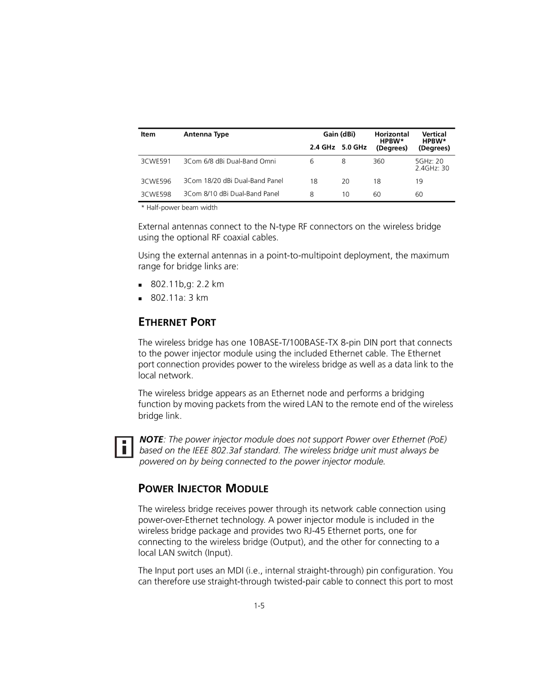
Item | Antenna Type | Gain (dBi) | Horizontal | Vertical | |
|
| 2.4 GHz | 5.0 GHz | HPBW* | HPBW* |
|
| (Degrees) | (Degrees) | ||
|
|
|
|
|
|
3CWE591 | 3Com 6/8 dBi | 6 | 8 | 360 | 5GHz: 20 |
|
|
|
|
| 2.4GHz: 30 |
3CWE596 | 3Com 18/20 dBi | 18 | 20 | 18 | 19 |
3CWE598 | 3Com 8/10 dBi | 8 | 10 | 60 | 60 |
|
|
|
|
| |
* |
|
|
|
| |
External antennas connect to the
Using the external antennas in a
802.11b,g: 2.2 km
802.11a: 3 km
ETHERNET PORT
The wireless bridge has one
The wireless bridge appears as an Ethernet node and performs a bridging function by moving packets from the wired LAN to the remote end of the wireless bridge link.
NOTE: The power injector module does not support Power over Ethernet (PoE) based on the IEEE 802.3af standard. The wireless bridge unit must always be powered on by being connected to the power injector module.
POWER INJECTOR MODULE
The wireless bridge receives power through its network cable connection using
The Input port uses an MDI (i.e., internal