8-PIN DIN CONNECTOR PINOUT
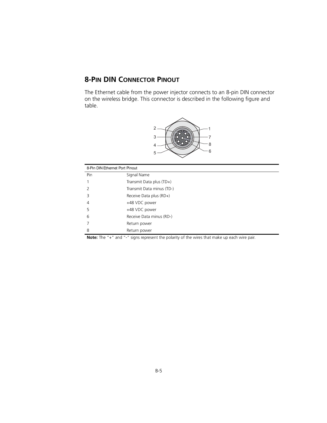
The Ethernet cable from the power injector connects to an
| 2 | 1 |
| 3 | 7 |
| 4 | 8 |
| 5 | 6 |
|
| |
|
| |
Pin | Signal Name |
|
1 | Transmit Data plus (TD+) |
|
2 | Transmit Data minus |
|
3 | Receive Data plus (RD+) |
|
4 | +48 VDC power |
|
5 | +48 VDC power |
|
6 | Receive Data minus |
|
7 | Return power |
|
8 | Return power |
|
Note: The “+” and