TESTING BASIC LINK OPERATION
Set up the units over a very short range (15 to 25 feet), either outdoors or indoors. Connect the units as indicated in this chapter and be sure to perform all the basic configuration tasks outlined in Chapter 4, “Initial Configuration.” When you are satisfied that the links are operating correctly, proceed to mount the units in their intended locations.
MOUNT THE UNIT
The bridge can be mounted on the following types of surfaces:
Pole
Wall
CAUTION: The bridge is intended for outdoor use only. Do not install the bridge ! indoors.
USING THE POLE-MOUNTING BRACKET
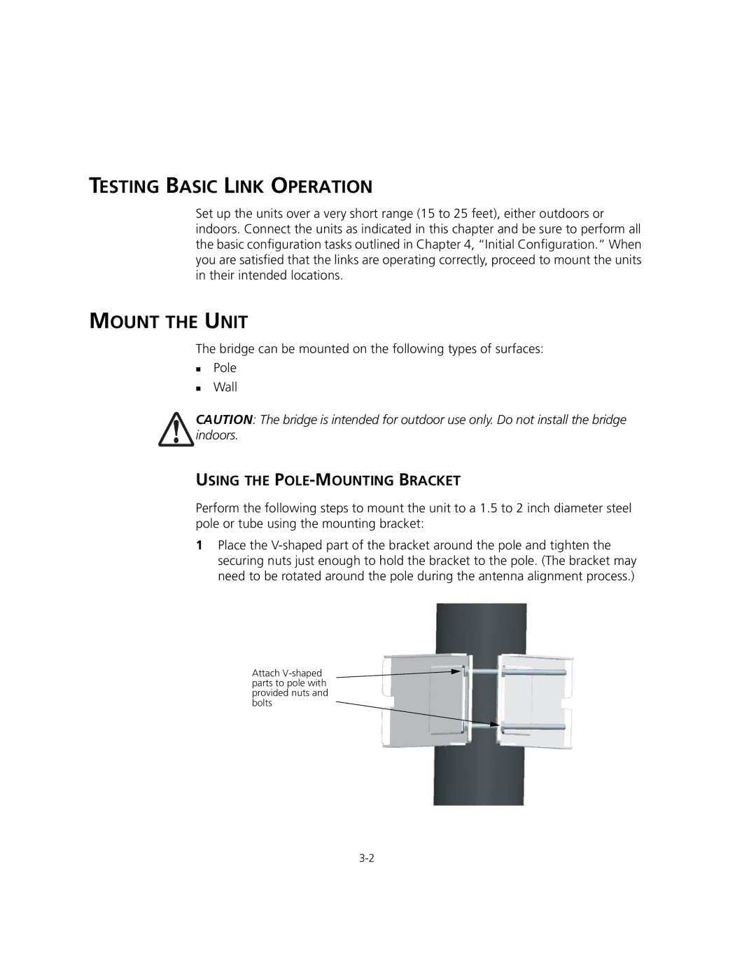
Perform the following steps to mount the unit to a 1.5 to 2 inch diameter steel pole or tube using the mounting bracket:
1 Place the
Attach
