•Be sure there is enough clearance from buildings and that no building construction may eventually block the path.
•Check the topology of the land between the antennas using topographical maps, aerial photos, or even satellite image data (software packages are available that may include this information for your area)
•Avoid a path that may incur temporary blockage due to the movement of cars, trains, or aircraft.
ANTENNA HEIGHT
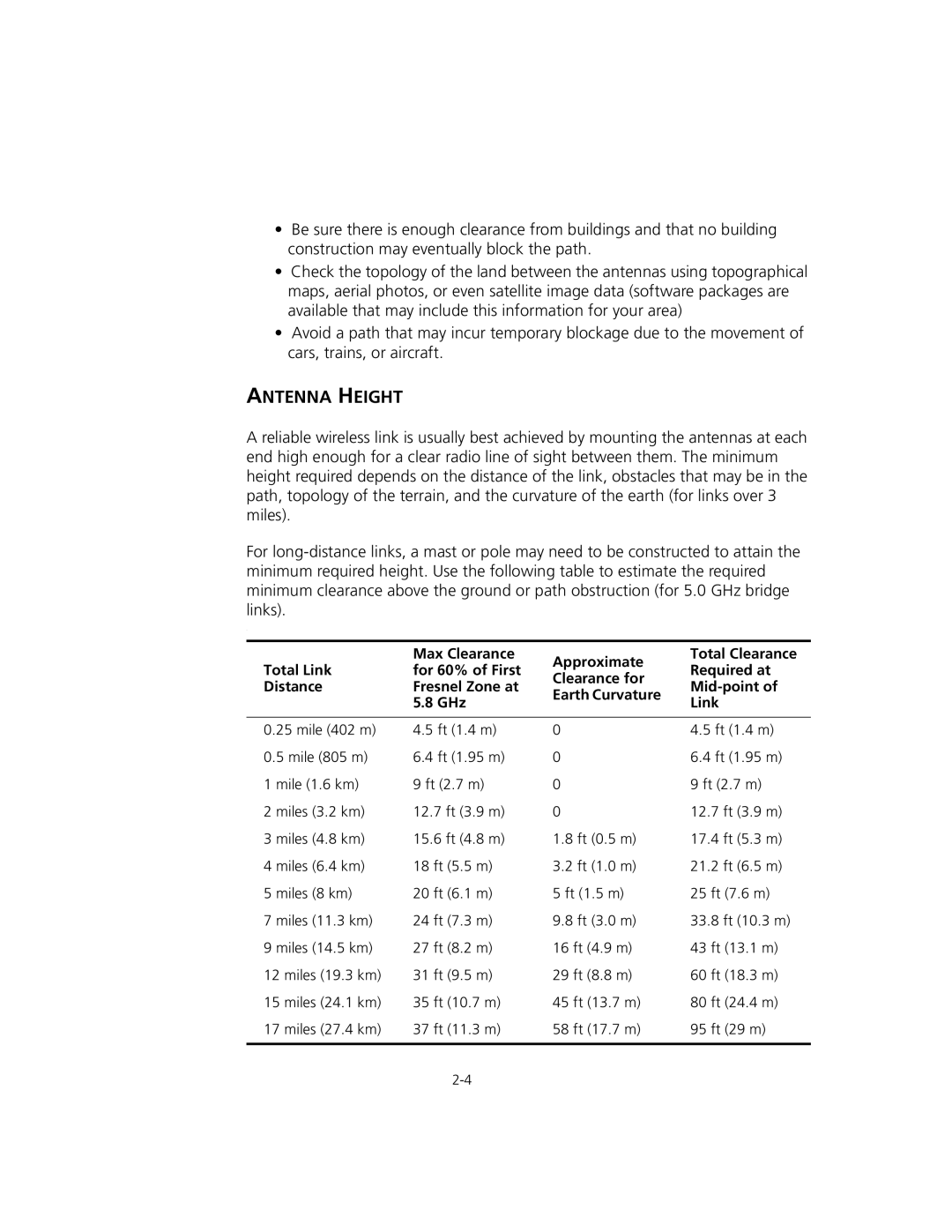
A reliable wireless link is usually best achieved by mounting the antennas at each end high enough for a clear radio line of sight between them. The minimum height required depends on the distance of the link, obstacles that may be in the path, topology of the terrain, and the curvature of the earth (for links over 3 miles).
For
.
| Max Clearance | Approximate | Total Clearance | |
Total Link | for 60% of First | Required at | ||
Clearance for | ||||
Distance | Fresnel Zone at | |||
Earth Curvature | ||||
| 5.8 GHz | Link | ||
|
| |||
|
|
|
| |
0.25 mile (402 m) | 4.5 ft (1.4 m) | 0 | 4.5 ft (1.4 m) | |
0.5 mile (805 m) | 6.4 ft (1.95 m) | 0 | 6.4 ft (1.95 m) | |
1 mile (1.6 km) | 9 ft (2.7 m) | 0 | 9 ft (2.7 m) | |
2 miles (3.2 km) | 12.7 ft (3.9 m) | 0 | 12.7 ft (3.9 m) | |
3 miles (4.8 km) | 15.6 ft (4.8 m) | 1.8 ft (0.5 m) | 17.4 ft (5.3 m) | |
4 miles (6.4 km) | 18 ft (5.5 m) | 3.2 ft (1.0 m) | 21.2 ft (6.5 m) | |
5 miles (8 km) | 20 ft (6.1 m) | 5 ft (1.5 m) | 25 ft (7.6 m) | |
7 miles (11.3 km) | 24 ft (7.3 m) | 9.8 ft (3.0 m) | 33.8 ft (10.3 m) | |
9 miles (14.5 km) | 27 ft (8.2 m) | 16 ft (4.9 m) | 43 ft (13.1 m) | |
12 miles (19.3 km) | 31 ft (9.5 m) | 29 ft (8.8 m) | 60 ft (18.3 m) | |
15 miles (24.1 km) | 35 ft (10.7 m) | 45 ft (13.7 m) | 80 ft (24.4 m) | |
17 miles (27.4 km) | 37 ft (11.3 m) | 58 ft (17.7 m) | 95 ft (29 m) | |
|
|
|
|