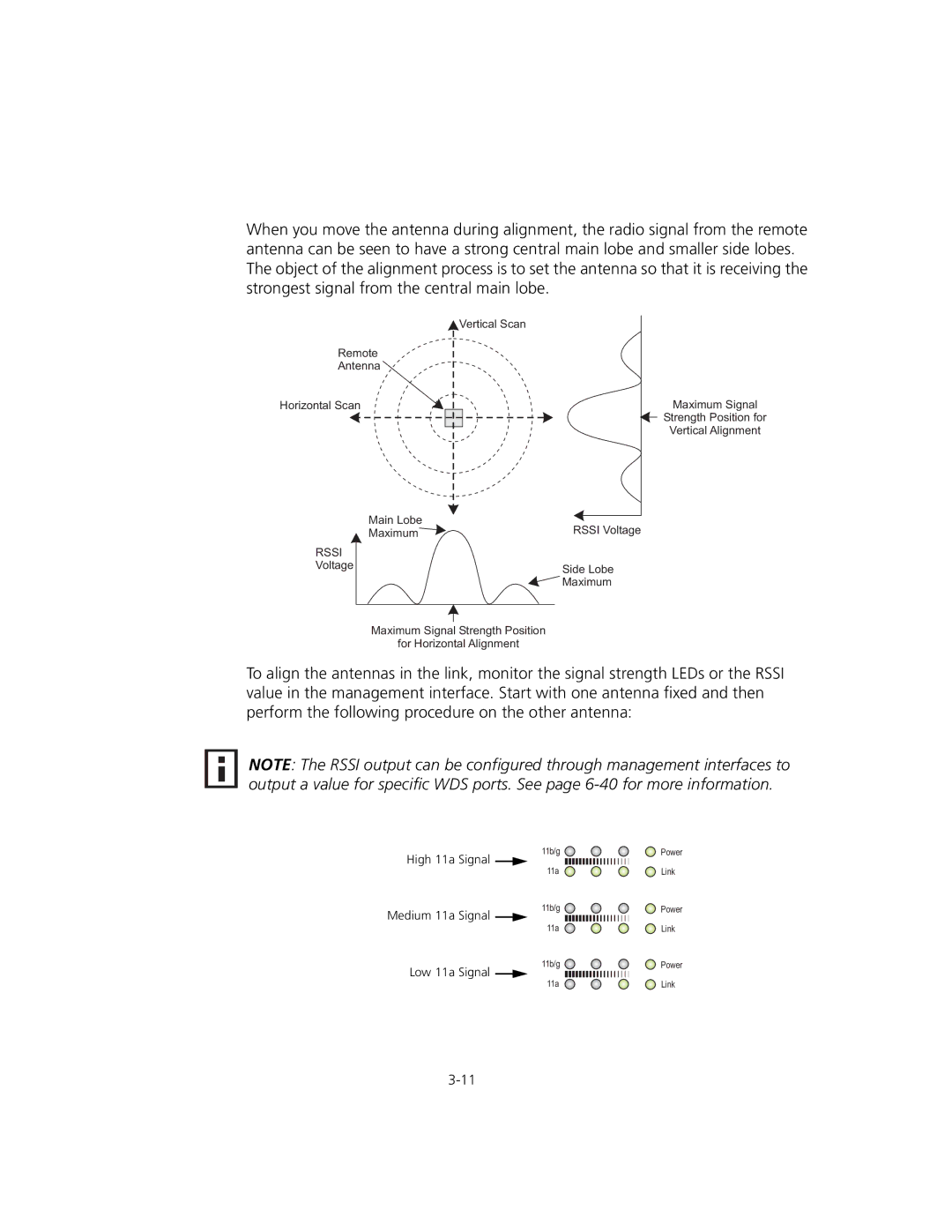
When you move the antenna during alignment, the radio signal from the remote antenna can be seen to have a strong central main lobe and smaller side lobes. The object of the alignment process is to set the antenna so that it is receiving the strongest signal from the central main lobe.
Vertical Scan
Remote
Antenna
Horizontal Scan
Main Lobe
| Maximum | RSSI Voltage |
RSSI |
|
|
Voltage |
| Side Lobe |
|
| |
|
| Maximum |
|
|
|
Maximum Signal
Strength Position for
Vertical Alignment
Maximum Signal Strength Position
for Horizontal Alignment
To align the antennas in the link, monitor the signal strength LEDs or the RSSI value in the management interface. Start with one antenna fixed and then perform the following procedure on the other antenna:
NOTE: The RSSI output can be configured through management interfaces to output a value for specific WDS ports. See page
High 11a | Signal | 11b/g | Power |
|
| ||
|
| 11a | Link |
Medium 11a | Signal | 11b/g | Power |
|
| ||
|
| 11a | Link |
Low 11a | Signal | 11b/g | Power |
|
| ||
|
| 11a | Link |