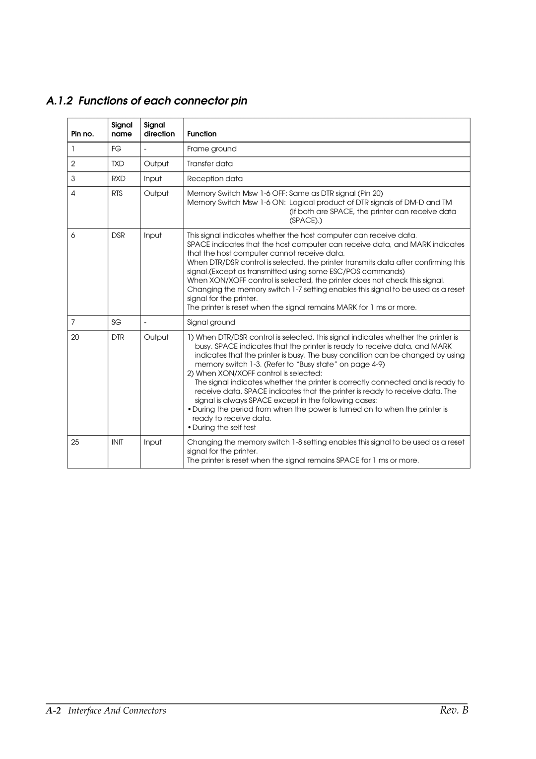
A.1.2 Functions of each connector pin
| Signal | Signal |
|
Pin no. | name | direction | Function |
|
|
|
|
1 | FG | - | Frame ground |
|
|
|
|
2 | TXD | Output | Transfer data |
|
|
|
|
3 | RXD | Input | Reception data |
|
|
|
|
4 | RTS | Output | Memory Switch Msw |
|
|
| Memory Switch Msw |
|
|
| (If both are SPACE, the printer can receive data |
|
|
| (SPACE).) |
|
|
|
|
6 | DSR | Input | This signal indicates whether the host computer can receive data. |
|
|
| SPACE indicates that the host computer can receive data, and MARK indicates |
|
|
| that the host computer cannot receive data. |
|
|
| When DTR/DSR control is selected, the printer transmits data after confirming this |
|
|
| signal.(Except as transmitted using some ESC/POS commands) |
|
|
| When XON/XOFF control is selected, the printer does not check this signal. |
|
|
| Changing the memory switch |
|
|
| signal for the printer. |
|
|
| The printer is reset when the signal remains MARK for 1 ms or more. |
|
|
|
|
7 | SG | - | Signal ground |
|
|
|
|
20 | DTR | Output | 1) When DTR/DSR control is selected, this signal indicates whether the printer is |
|
|
| busy. SPACE indicates that the printer is ready to receive data, and MARK |
|
|
| indicates that the printer is busy. The busy condition can be changed by using |
|
|
| memory switch |
|
|
| 2) When XON/XOFF control is selected: |
|
|
| The signal indicates whether the printer is correctly connected and is ready to |
|
|
| receive data. SPACE indicates that the printer is ready to receive data. The |
|
|
| signal is always SPACE except in the following cases: |
|
|
| •During the period from when the power is turned on to when the printer is |
|
|
| ready to receive data. |
|
|
| •During the self test |
|
|
|
|
25 | INIT | Input | Changing the memory switch |
|
|
| signal for the printer. |
|
|
| The printer is reset when the signal remains SPACE for 1 ms or more. |
|
|
|
|
Rev. B |