| Application | Xon/Xoff | DTR/DSR | RTS/CTR | |
TM side | control | (except OPOS) | (DOS, Windows | (DOS, Windows (hardware | |
|
|
| (only OPOS)) | control: Windows driver)) | |
control setting |
|
|
| ||
|
|
|
|
|
|
Xon/Xoff |
|
| Not available | — | — |
|
|
|
|
| |
DTR/DSR |
| 1 | — | Type A or B | Type B |
|
|
|
|
|
|
|
| 2 | — | Type A or B | Type A or B |
|
|
|
|
|
|
Connection procedure
1.Press the connector on the end of the interface cable firmly onto the interface connector located on the connector panel.
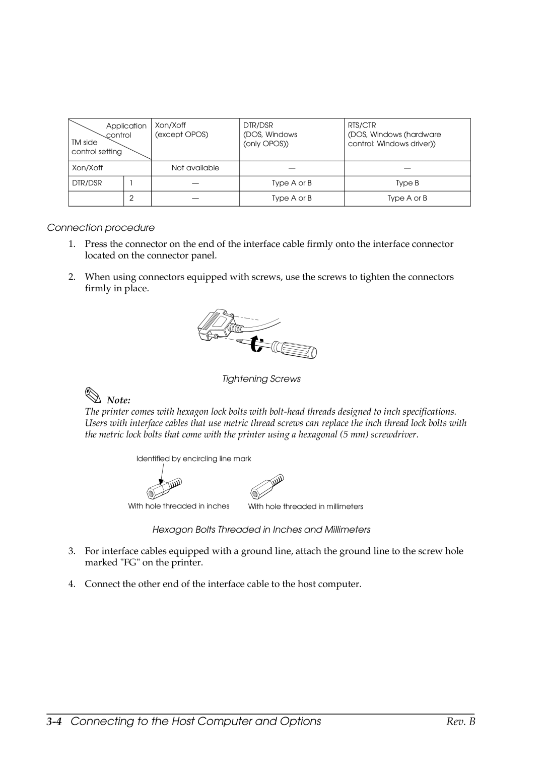
2.When using connectors equipped with screws, use the screws to tighten the connectors firmly in place.
Tightening Screws
Note:
The printer comes with hexagon lock bolts with
Identified by encircling line mark
With hole threaded in inches | With hole threaded in millimeters |
Hexagon Bolts Threaded in Inches and Millimeters
3.For interface cables equipped with a ground line, attach the ground line to the screw hole marked "FG" on the printer.
4.Connect the other end of the interface cable to the host computer.
| Rev. B |