Connection procedure
1.Attach the locking wire saddle at the location shown in figure below.
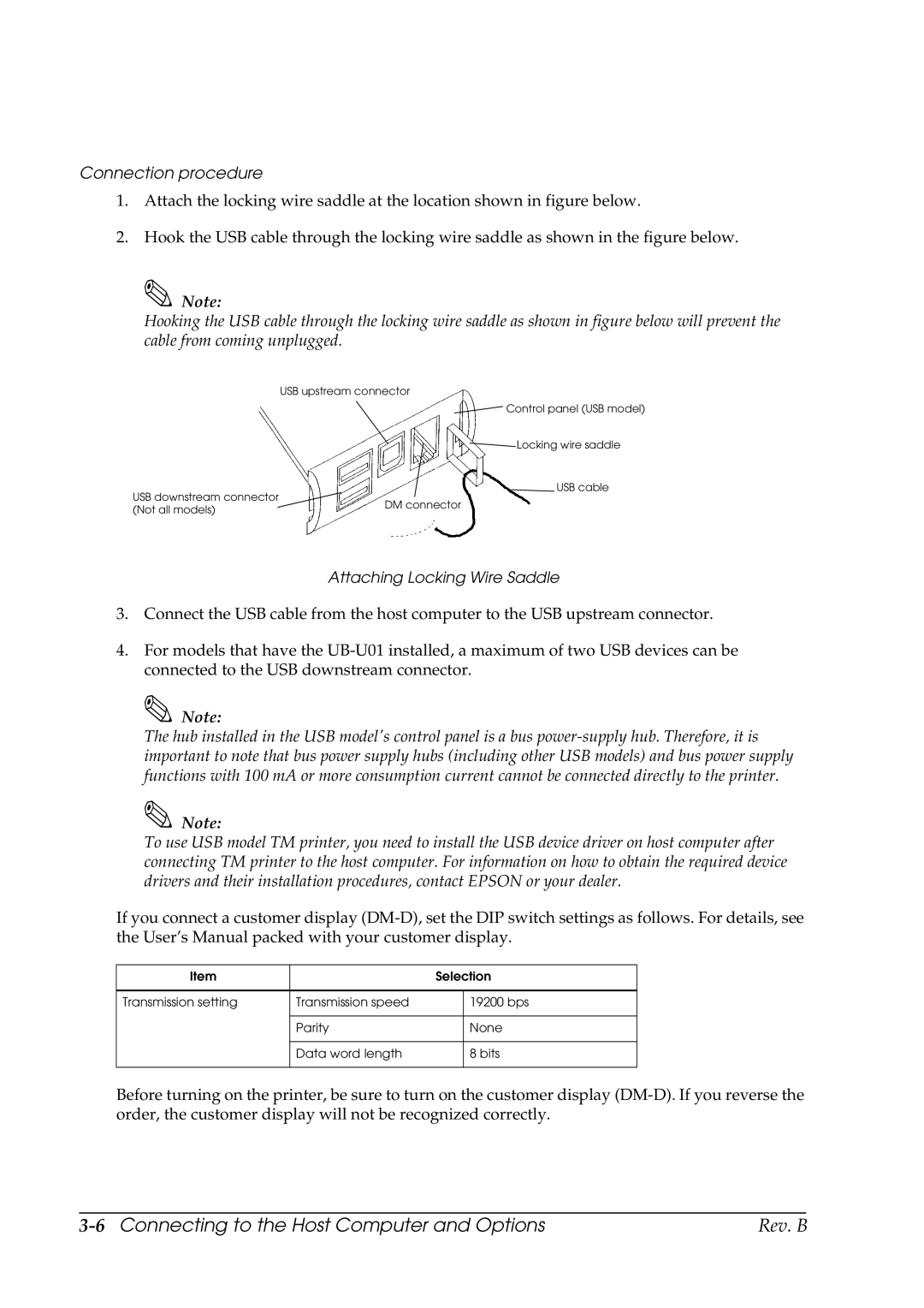
2.Hook the USB cable through the locking wire saddle as shown in the figure below.
![]() Note:
Note:
Hooking the USB cable through the locking wire saddle as shown in figure below will prevent the cable from coming unplugged.
USB upstream connector
Control panel (USB model)
Locking wire saddle
USB cable
USB downstream connector |
| |
DM connector | ||
(Not all models) | ||
|
Attaching Locking Wire Saddle
3.Connect the USB cable from the host computer to the USB upstream connector.
4.For models that have the
![]() Note:
Note:
The hub installed in the USB model's control panel is a bus
![]() Note:
Note:
To use USB model TM printer, you need to install the USB device driver on host computer after connecting TM printer to the host computer. For information on how to obtain the required device drivers and their installation procedures, contact EPSON or your dealer.
If you connect a customer display
Item |
| Selection | |
|
|
|
|
Transmission setting | Transmission speed |
| 19200 bps |
|
|
|
|
| Parity |
| None |
|
|
|
|
| Data word length |
| 8 bits |
|
|
|
|
Before turning on the printer, be sure to turn on the customer display
| Rev. B |