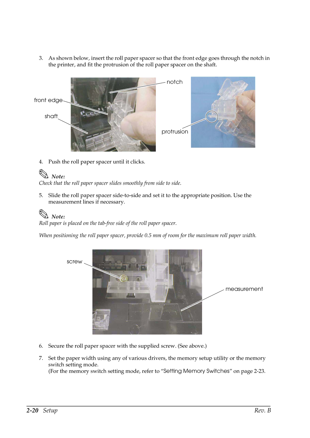
3.As shown below, insert the roll paper spacer so that the front edge goes through the notch in the printer, and fit the protrusion of the roll paper spacer on the shaft.
notch
front edge
shaft
protrusion
4. Push the roll paper spacer until it clicks.
Note:
Check that the roll paper spacer slides smoothly from side to side.
5.Slide the roll paper spacer
Note:
Roll paper is placed on the
When positioning the roll paper spacer, provide 0.5 mm of room for the maximum roll paper width.
screw
measurement
6.Secure the roll paper spacer with the supplied screw. (See above.)
7.Set the paper width using any of various drivers, the memory setup utility or the memory switch setting mode.
(For the memory switch setting mode, refer to “Setting Memory Switches” on page
| Rev. B |