TM-L90/TM-L90 with Peeler Technical Reference Guide
2.9 Memory Switch Functions
This printer has the following software switches, called memory switches, in the
•Msw 1, Msw 2, Msw 8
•Customized values
•Serial communication conditions
These settings can be made by the memory switch setup utility (see page
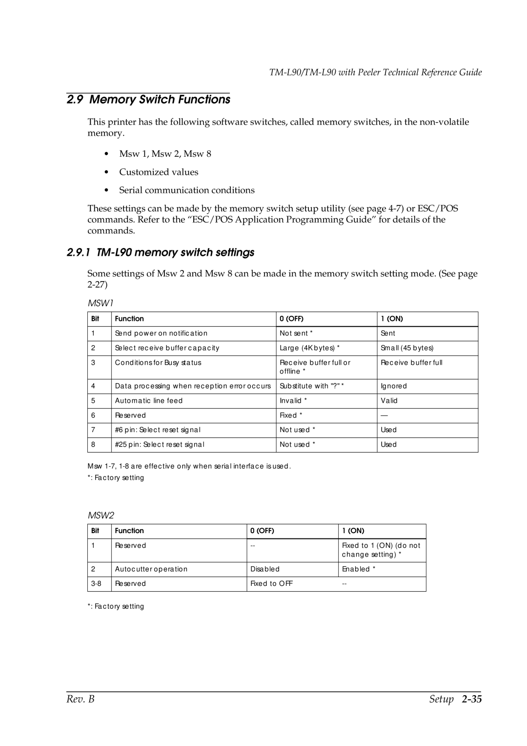
2.9.1 TM-L90 memory switch settings
Some settings of Msw 2 and Msw 8 can be made in the memory switch setting mode. (See page
MSW1
Bit | Function | 0 (OFF) | 1 (ON) |
|
|
|
|
1 | Send power on notification | Not sent * | Sent |
|
|
|
|
2 | Select receive buffer capacity | Large (4K bytes) * | Small (45 bytes) |
|
|
|
|
3 | Conditions for Busy status | Receive buffer full or | Receive buffer full |
|
| offline * |
|
|
|
|
|
4 | Data processing when reception error occurs | Substitute with "?" * | Ignored |
|
|
|
|
5 | Automatic line feed | Invalid * | Valid |
|
|
|
|
6 | Reserved | Fixed * | — |
|
|
|
|
7 | #6 pin: Select reset signal | Not used * | Used |
|
|
|
|
8 | #25 pin: Select reset signal | Not used * | Used |
|
|
|
|
Msw
MSW2
Bit | Function | 0 (OFF) | 1 (ON) |
|
|
|
|
1 | Reserved | Fixed to 1 (ON) (do not | |
|
|
| change setting) * |
|
|
|
|
2 | Autocutter operation | Disabled | Enabled * |
|
|
|
|
Reserved | Fixed to OFF | ||
|
|
|
|
*: Factory setting
Rev. B | Setup |