Names of parts
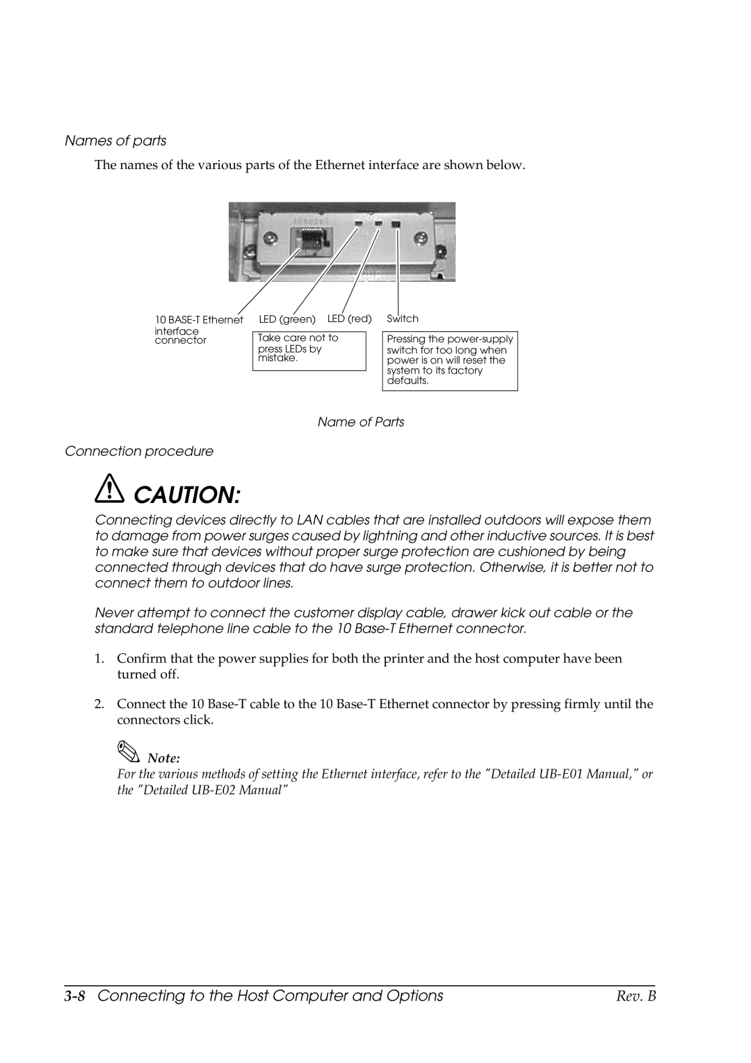
The names of the various parts of the Ethernet interface are shown below.
10
interface connector
Take care not to
press LEDs by mistake.
Pressing the
Name of Parts
Connection procedure
![]() CAUTION:
CAUTION:
Connecting devices directly to LAN cables that are installed outdoors will expose them to damage from power surges caused by lightning and other inductive sources. It is best to make sure that devices without proper surge protection are cushioned by being connected through devices that do have surge protection. Otherwise, it is better not to connect them to outdoor lines.
Never attempt to connect the customer display cable, drawer kick out cable or the standard telephone line cable to the 10
1.Confirm that the power supplies for both the printer and the host computer have been turned off.
2.Connect the 10
![]() Note:
Note:
For the various methods of setting the Ethernet interface, refer to the "Detailed
Rev. B |