Note:
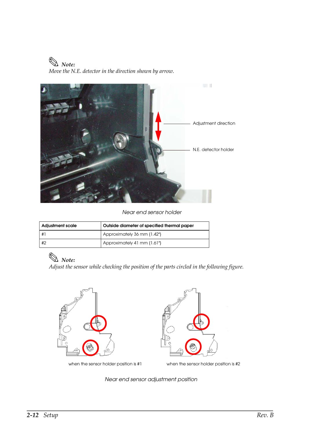
Move the N.E. detector in the direction shown by arrow.
![]()
![]() Adjustment direction
Adjustment direction
N.E. detector holder
| Near end sensor holder |
|
|
Adjustment scale | Outside diameter of specified thermal paper |
|
|
#1 | Approximately 36 mm {1.42"} |
|
|
#2 | Approximately 41 mm {1.61"} |
|
|
Note:
Adjust the sensor while checking the position of the parts circled in the following figure.
when the sensor holder position is #1 | when the sensor holder position is #2 |
Near end sensor adjustment position
| Rev. B |