Appendix
16.4PCIe slot to CPUMEMR assignment
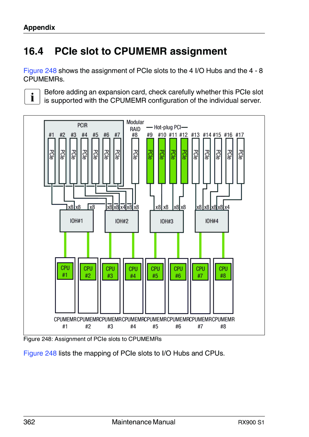
Figure 248 shows the assignment of PCIe slots to the 4 I/O Hubs and the 4 - 8 CPUMEMRs.
IBefore adding an expansion card, check carefully whether this PCIe slot is supported with the CPUMEMR configuration of the individual server.
|
|
| PCIR |
|
|
| Modular |
|
|
|
|
|
|
|
|
|
|
|
|
| RAID |
|
|
|
|
|
| ||
|
|
|
|
|
|
|
|
|
|
|
|
| ||
|
|
|
|
|
|
|
|
|
|
|
|
|
| |
|
|
|
|
|
|
|
|
|
|
|
|
|
| |
#1 | #2 | #3 | #4 | #5 | #6 | #7 | #8 | #9 | #10 #11 #12 | #13 | #14 #15 | #16 | #17 | |
PCIe
PCIe
PCIe
PCIe
PCIe
PCIe
PCIe
PCIe
PCIe
PCIe
PCIe
PCIe
PCIe
PCIe
PCIe
PCIe
PCIe
x8![]() x8
x8 ![]() x8
x8
IOH#1
x8 x8 x4 x8 x8
IOH#2
x8 x8 x8 x8
IOH#3
x8 x8 x8 x8 x4
IOH#4
CPU #1
CPU #2
CPU | CPU | CPU | CPU | CPU |
#3 | #4 | #5 | #6 | #7 |
CPU #8
CPUMEMRCPUMEMRCPUMEMRCPUMEMRCPUMEMRCPUMEMRCPUMEMRCPUMEMR
#1 | #2 | #3 | #4 | #5 | #6 | #7 | #8 |
Figure 248: Assignment of PCIe slots to CPUMEMRs
Figure 248 lists the mapping of PCIe slots to I/O Hubs and CPUs.
362 | Maintenance Manual | RX900 S1 |
