This soft copy for use by IBM employees only.

7.1.4 Configuring a Local Multi-Switch Network for CIP

In this scenario, we add another 8285 to our network, representing perhaps a departmental work group on a different floor. To accommodate the new high-speed connection, we add an 8285 Expansion Chassis to our base configuration. Now our network diagram looks like the following:
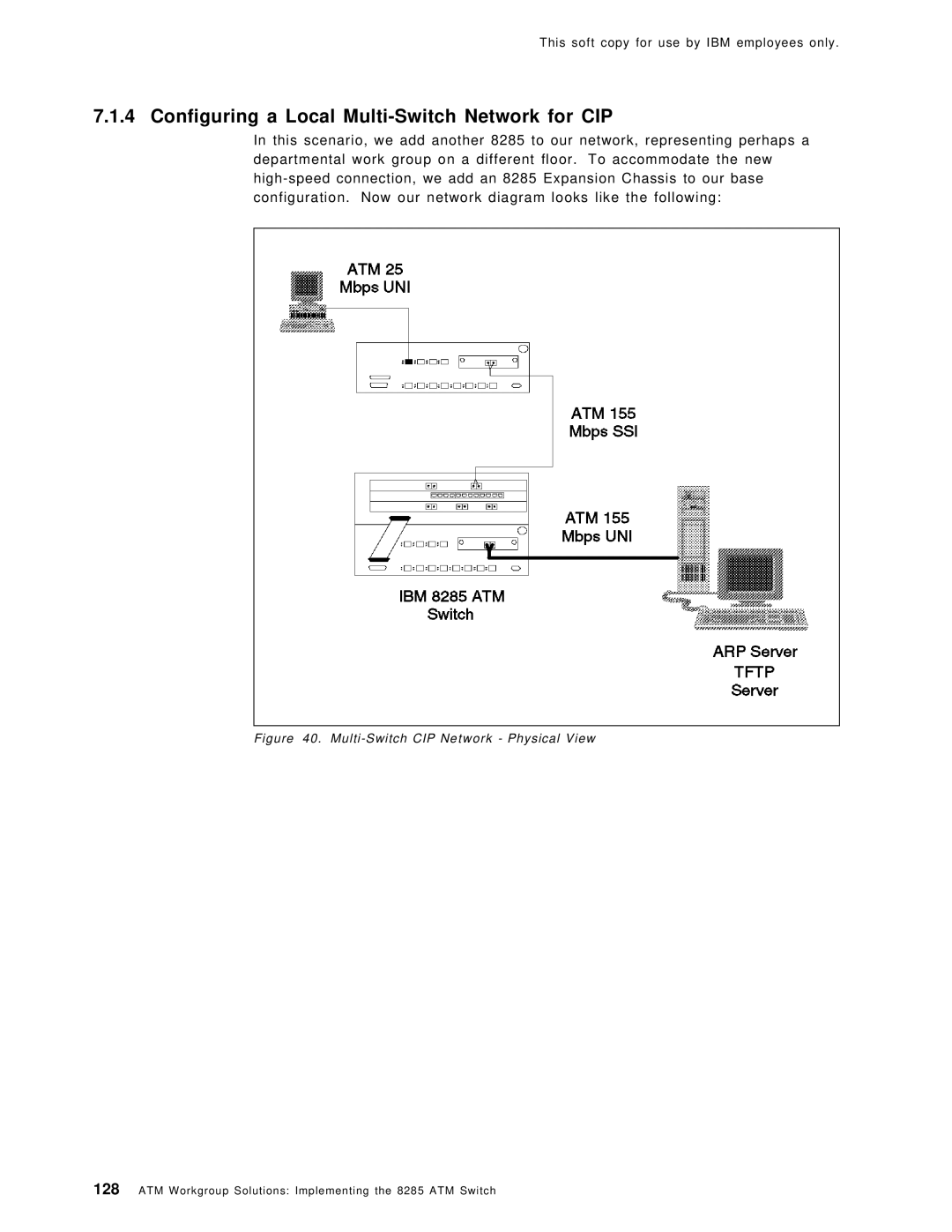
Figure 40. Multi-Switch CIP Network - Physical View

128ATM Workgroup Solutions: Implementing the 8285 ATM Switch

Page 144
Image 144
IBM SG24-4817-00 manual Configuring a Local Multi-Switch Network for CIP, Multi-Switch CIP Network Physical View