FrameSaver SLV
Warranty, Sales, Service, and Training Information
Copyright 2002 Paradyne Corporation All rights reserved
Document Feedback
Trademarks
Contents
ConfigurationTProcedures
Configuration Options
September
Configuring the FrameSaver SLV Router
Iii
Security and Logins
Operation and Maintenance
Troubleshooting
Lamp Test
Setting Up NetScout Manager Plus for FrameSaver Devices
Setting Up Network Health for FrameSaver Devices
Menu HierarchyT
Vii
Snmp MIBs and Traps, and Rmon Alarm Defaults
Router CLI TCommands, Codes, and Designations
Viii
Router Command Line Summaries and Shortcuts
Connectors, Cables, and Pin Assignments
Technical Specifications Equipment List
Index
Purpose and Intended Audience
Document Organization
Section Description
Xii
Section Description
Product-Related Documents
Xiii
Document Number Document Title
Conventions Used
Xiv
About the FrameSaver SLV
System Overview
CSU/DSU-Specific Features
Router-Specific Features
About the FrameSaver SLV
FrameSaver Diagnostic and SLM Feature Sets
FrameSaver Diagnostic Feature Set
FrameSaver SLV Feature Router
Maximum Number of PVCs and Management PVCs Supported
Through 120 Connections PVCs Dedicated Management
About the FrameSaver SLV
About the FrameSaver SLV
Additional FrameSaverTSLV 9126-II and 9128-II Features
Additional FrameSaver SLV 9128-II Features
FrameSaver SLM Feature Set
OpenLane SLM System
NetScout Manager Plus and NetScout Probes
User Interface and Basic Operation
Procedure
Logging On
If your login was Hen
Main Menu
Select
Screen Work Areas
Screen Format Description
Navigating the Screens
Keyboard Keys
Press
Function Keys
For the screen Select Function Press Enter to
Switching Between Screen Areas
Selecting from a Menu
Screen Contents
Selecting a Field
Entering Information
Navigating the Router’s CLI
CLI Keyboard Keys
Configuration Procedures
Basic Configuration
Configuration Menu
Isdn
Configuration Option Areas
Configuration Option Area Description
Accessing and Displaying Configuration Options
Main Menu → Configuration
Changing Configuration Options
Configuration → PVC Connections
Saving Configuration Options
Configuration Options
Configuration Options
Using the Easy Install Feature
Main Menu → Easy Install
Easy Install Screen Example
Using RIP with FrameSaver SLV CSU/DSUs
Configuration → Data Ports→ Dlci Records
Entering System Information and Setting the System Clock
Main Menu → Control→ System Information
If the selection is Enter
Setting Up the Modem
Setting Up Call Directories for Trap Dial-Out
Main Menu → Control→ Modem Call Directories
Valid characters include For
Setting Up to Use the Modem PassThru Feature
Setting Up Auto-Configuration
Main Menu → Auto-Configuration
Auto-Configuration Screen Example
Selecting a Frame Relay Discovery Mode
Main Menu → Auto-Configuration→Frame Relay Discovery Mode
Discovery Mode Configuration Description
Only applies to models with
Discovery Mode Configuration Description
Automatically Removing a Circuit
Setting Up Dial Backup
Setting Up the DBM Physical Interface
Main Menu → Configuration → Isdn → Physical
Setting Up Automatic Backup Configuration
If you select Then
Following prompt When Appears If you select
Remove Alternate
Destinations
From PVCs
Delete unused
Main Menu → Configuration → Isdn → Link Profiles
For Originating a Backup Call For Answering a Backup Call
Modifying Isdn Link Profiles
Restricting Automatic Backup and Configuring Backup Timers
Main Menu → Configuration → Auto-Backup Criteria
Configuring the DBM Interface to Send Snmp Traps
Assigning DLCIs to a Backup Group
PVC Backup Over the Network Interface
Setting Up Back-to-Back Operation
Changing Operating Mode
Main Menu → Control→ Change Operating Mode
Configuration Option Tables
Configuring the Overall System
Configuring Frame Relay and LMI for the System CSU/DSUs
Main Menu → Configuration → System → Frame Relay and LMI
System Frame Relay and LMI Options 1
System Frame Relay and LMI Options 2
LMI Status Enquiry N1 Possible Settings 1, 2, 3, 4
LMI Heartbeat T1 Possible Settings 5, 10, 15, 20, 25
System Frame Relay and LMI Options 3
System Frame Relay and LMI Options 4
Configuring Class of Service Definitions
Field Setting After RfcCodePoints Selected
Class of Service Definitions
Class of Svc Name
Measure Latency & Availability
Code Points Assigned
Code Point Definitions
Code Point Definitions
Code Pnt
Name
Configuring Service Level Verification Options
Service Level Verification Options 1
SLV Type Available Settings Standard, COS 1-COS
SLV Sample Interval secs
Service Level Verification Options 2
Dlci Down on SLV Timeout
SLV Timeout Error Event Threshold
SLV Timeout Clearing Event Threshold
Service Level Verification Options 3
SLV Latency Clearing Event Threshold
SLV Packet Size bytes
Configuring General System Options
Main Menu → Configuration → System→ General
Test Timeout
General System Options 1
General System Options 2
System Alarm Relay
General System Options 3
Configuring Physical Interfaces
Configuring the Network Interface
Main Menu → Configuration → Network→ Physical
Network Physical Interface Options 1
Line Build Out LBO Possible Settings 0.0, -7.5, -15
Network Physical Interface Options 2
Bit Stuffing
Transmit Timing
Network Initiated Dclb Possible Settings Disable, V.54&ANSI
Network Physical Interface Options 3
Network Initiated PLB
Ansi Performance Report Messages
Network Physical Interface Options 4
Circuit Identifier
Configuring a User Data Port CSU/DSUs
Main Menu → Configuration → Data Ports→ Physical
Port Use Possible Settings Frame Relay, Synchronous Data
Data Port Physical Interface Options 1
Data Port Physical Interface Options 2
Max Port Rate Kbps
Port Base Rate Kbps
Transmit Clock Source
Data Port Physical Interface Options 3
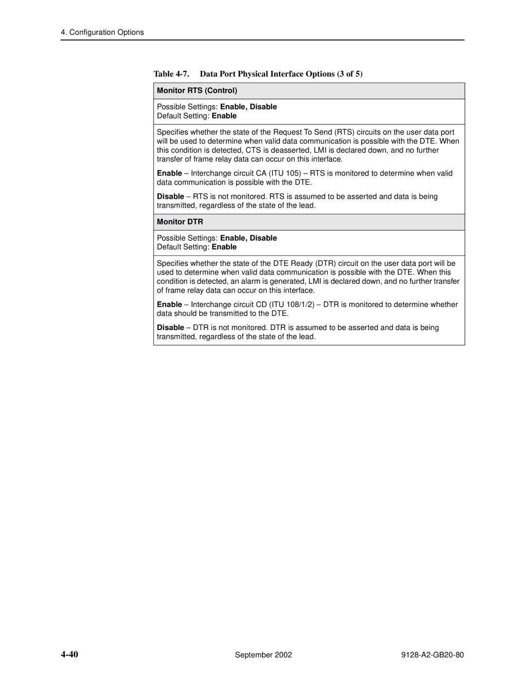
Monitor RTS Control
Monitor DTR
Data Port Physical Interface Options 4
Port DTE Initiated Loopbacks
Invert Transmit and Receive Data
Action on Network Yellow Alarm
Data Port Physical Interface Options 5
Configuring the DSX-1 Interface
Main Menu → Configuration → DSX-1
DSX-1 Physical Interface Options 1
Interface Status
DSX-1 Physical Interface Options 2
Send All Ones on DSX-1 Failure
Configuring the Isdn DBM Interface
Service Profile ID Spid 1 or
Isdn BRI DBM Physical Interface Options
Local Phone Number 1 or
Switch Type Possible Settings NI-2, ATT4ESS, ATT5ESS
10. Isdn PRI DBM Physical Interface Options 1
Local Phone Number
10. Isdn PRI DBM Physical Interface Options 2
10. Isdn PRI DBM Physical Interface Options 3
Setting Up Isdn Link Profiles
Main Menu → Configuration → Isdn → Isdn Link Profiles
11. Isdn Link Profile Options 1
Link Name
11. Isdn Link Profile Options 2
Outbound Phone Number
Inbound Calling ID 1 or
Maximum Link Rate Kbps
Assigning Time Slots/Cross Connections
11. Isdn Link Profile Options 3
Caller Identification Method
Alternate Outbound Phone Number
Assigning Frame Relay Time Slots to the Network Interface
Frame Relay Network Time Slot Assignment Screen Example
Value Meaning
Assigning DSX-1 Time Slots to the Network Interface
Time Slot Assignment Rule
Ntt
DSX-1 to Network Time Slot Assignment Screen Example
Ime Slot Assignment Rules
DSX-1 Signaling Assignments and Trunk Conditioning
RBS
Idle
PLAR3idle
Synchronous Data Port Assignment Screen Example
Sync Data Port Assignment
Clearing Assignments
Physical Interface Options
Configuring Frame Relay for an Interface
13. Interface Frame Relay Options 1
LMI
13. Interface Frame Relay Options 2
Traffic Policing
LMI Parameters
Frame Relay DS0s Base Rate
13. Interface Frame Relay Options 3
Manually Configuring Dlci Records
14. Dlci Record Options 1
Dlci Number
14. Dlci Record Options 2
CIR bps
Committed Burst Size Bc Bits
14. Dlci Record Options 3
Excess Burst Size Bits
Dlci Priority
Outbound Management Priority
Backup Group Possible Settings A, B, C, . . . Z, None
14. Dlci Record Options 4
Configuring PVC Connections
Main Menu → Configuration → PVC Connections
15. PVC Connection Options 1
Source Dlci
15. PVC Connection Options 2
Source Edlci
Primary Destination Link
Primary Destination Dlci
15. PVC Connection Options 3
Primary Destination Edlci
Alternate Destination Link
Alternate Destination Dlci
15. PVC Connection Options 4
Alternate Destination Edlci
Configuring the IP Path List
Main Menu → Configuration → IP Path List Static
16. IP Path List
Enter IP Address press ESC to abort ... FWD No
Setting Up Management and Communication Options
Configuring Node IP Information
17. Node IP Options 1
TS Access Management Link
17. Node IP Options 2
17. Node IP Options 3
TS Management Snmp Validation
Configuring Management PVCs
18. Management PVC Options 1
18. Management PVC Options 2
Payload Managed
Set DE
18. Management PVC Options 3
Primary Dlci
18. Management PVC Options 4
Primary Edlci
18. Management PVC Options 5
Alternate Dlci
Alternate Edlci
18. Management PVC Options 6
Encapsulation
Configuring General Snmp Management
Name 1 Access
19. General Snmp Management Options 1
Snmp Management
Configuring Telnet and/or FTP Session Support
Name 2 Access
19. General Snmp Management Options 2
Telnet Login Required
20. Telnet and FTP Session Options 1
Telnet Session
20. Telnet and FTP Session Options 2
Configuring Snmp NMS Security
21. Snmp NMS Security Options 1
NMS IP Validation
Number of Managers
Configuring Snmp Traps and Trap Dial-Out
21. Snmp NMS Security Options 2
22. Snmp Traps and Trap Dial-Out Options 1
22. Snmp Traps and Trap Dial-Out Options 2
Link Traps Possible Settings Disable, Up, Down, Both
22. Snmp Traps and Trap Dial-Out Options 3
Enterprise Specific Traps
Possible Settings Network, Ports, DBM, All, None
22. Snmp Traps and Trap Dial-Out Options 4
Dlci Traps on Interfaces Filter Selection Field
Rmon Traps
Dial-Out Delay TIme Min
22. Snmp Traps and Trap Dial-Out Options 5
Trap Dial-Out
Trap Disconnect
22. Snmp Traps and Trap Dial-Out Options 6
Alternate Dial-Out Directory
Latency Traps
IP SLV Availability Traps
Configuring Ethernet Management
23. Ethernet Management Options 1
23. Ethernet Management Options 2
Proxy ARP
Configuring the Communication Port
24. Communication Port Options 1
Character Length
Login Required
24. Communication Port Options 2
Parity
Stop Bits
24. Communication Port Options 3
24. Communication Port Options 4
RIP
Configuring the Modem Port
100
24. Communication Port Options 5
25. Modem Port Options 1
101
25. Modem Port Options 2
102
25. Modem Port Options 3
103
25. Modem Port Options 4
Configuring the Criteria for Automatic Backup
Main Menu → Configuration → Auto Backup Criteria
26. Auto Backup Criteria Options 1
104
26. Auto Backup Criteria Options 2
When Auto Backup Allowed
Backup Allowed Day From nnnn
Backup Allowed Day To nnnn
106
Configuring the FrameSaver SLV Router
FrameSaver SLV Router Overview
Network Interface
Ethernet
Address Resolution Protocol
IP Routing
Proxy ARP
Interface Configuration
Network Address Translation
IP Options Processing
Applications Supported by NAT
NAT Configuration Example
NAT Mapping Public IP Addresses Private IP Addresses
Save exit
Napt Configuration Example
Network Address Port Translation
Napt Mapping Public IP Address Private IP Addresses
Access-list 1 permit 10.1.3.0
Ip nat inside source list 1 interface se 0.x overload
Int ethernet 0 ip nat inside int serial 0.x ip nat outside
NAT and Napt Configuration Example
Ip nat inside source static 10.1.1.1
Dynamic Host Configuration Protocol Server
Dhcp Server with NAT Configuration Example
Public IP Addresses for NAT Private IP Addresses
Dhcp Server at Remote Site Configuration Example
Dhcp Relay Agent
Router Security
IP Router Filtering
Bridge Filtering
Provisioning the Router Interface
IP Filtering
Land Bug Prevention
Smurf Attack Prevention
Configuring the Router Using Terminal Emulation
Security and Logins
Limiting Access
Controlling Asynchronous Terminal Access
Set the configuration option
Limiting Dial-In Access via the Modem Port
Controlling Isdn Access
Disabling Isdn Access
Isdn Call Security
Controlling Telnet or FTP Access
Limiting Telnet Access
Limiting FTP Access
Has a Level-1 login and Level-2 telnet access has
Controlling Snmp Access
Disabling Snmp Access
Assigning Snmp Community Names and Access Levels
Limiting Snmp Access Through IP Addresses
Main Menu → Configuration →
General Snmp Management → Snmp Management Enable
Management and Communication →
Creating a Login
Main Menu → Control→ Administer Logins
Field Enter
Modifying a Login
Deleting a Login
Controlling Router CLI Access
Access Levels Command Modes
Largo
Changing Access Levels
Enable
Enable password password
End
Security and Logins September
Operation and Maintenance
Operation and Maintenance
Displaying System Information
Main Menu → Status → Identity
View this field To find
Viewing LEDs and Control Leads
Isdn DBM
FrameSaverTM SLV
FrameSaver SLV 9126 LEDs and Control Leads
Main Menu → Status → Display LEDs and Control Leads
Display LEDs & Control Leads Screen for a FrameSaver SLV
FrameSaver SLV 9128-II LEDs and Control Leads
Main Menu → Status → Display LEDs and Control Leads
LED Descriptions
General Status LEDs 1
Label Indiction Color What It Means
ALM
General Status LEDs 2
Contd
Model
9128-II
Network, DSX, or PRI Interface LEDs
Label Indication Color What It Means
User Data Port LED CSU/DSUs Only
Ethernet Port LED Routers Only
Control Lead Descriptions
Additional Control Leads Label Indication What It Means
Network Interface
User Data Port
Device Messages
Device Messages 1 What It Indicates What To Do
Seen at an FTP
Terminal
Device Messages 2 What It Indicates What To Do
See Changing Software on
Device Messages 3 What It Indicates What To Do
PVC
Device Messages 4 What It Indicates What To Do
Reset COM Port usage
Device Messages 5 What It Indicates What To Do
FrameSaver SLV
II only
Device Messages 6 What It Indicates What To Do
Status Information
Status Menu Example
Last System Reset Date and Time
System and Test Status Messages
Main Menu → Status → System and Test Status
Self-Test Results Messages
Change Operating Mode
Health and Status Messages
Health and Status Messages 1 What It Indicates
Isdn PRI DBM only
Health and Status Messages 2 What It Indicates
Frame relay link 1,2
FrameSaver SLV 9126-II or
Health and Status Messages 3 What It Indicates
Health and Status Messages 4 What It Indicates
Framerelaylink 1,2
Series Access Carrier only
Health and Status Messages 5 What It Indicates
PathIP Address Down
Nnnn, framerelaylink 1,2
Health and Status Messages 6 What It Indicates
Configuration→ Time Slot Assignment → Frame
Health and Status Messages 7 What It Indicates
Relay Network Assignments and an LMI failure is
Test Status Messages
Test Status Messages 1 What It Indicates
Dclb Active, framerelaylink 1 or
Framerelaylink 1 ,3
Test Status Messages 2 What It Indicates
Network LMI-Reported DLCIs Status
Main Menu → Status→ LMI Reported DLCIs
LMI-Reported DLCIs Status Screen Example
Tframe relay network, or
IP Path Connection Status
Main Menu → Status→ IP Path Connection Status
IP Path Connection Status Screen Example
11. IP Path Connection Status Field What It Indicates
PVC Connection Status
Main Menu → Status→ PVC Connection Status
PVC Connection Status Screen Example
12. PVC Connection Status 1 Field What It Indicates
MgmtPVCName
Edlci
12. PVC Connection Status 2 Field
Status What It Indicates
Time Slot Assignment Status
Displaying Network Time Slot Assignments
Main Menu → Status→ Timeslot Assignment Status → Network
Network Timeslot Assignment Status Screen Example
Cross Connect Status Field bottom Indicates
Displaying DSX-1 Time Slot Assignments
Main Menu → Status→ Timeslot Assignment Status→ DSX-1
DSX-1 Timeslot Assignment Status Screen Example
DBM Interface Status
Main Menu → Status→ DBM Interface Status
DBM Interface Status Screen Example
13. DBM Interface Status 1 Field What It Indicates
Invalid Call ID is displayed
Link Name Disabled
13. DBM Interface Status 2 Field What It Indicates
Awarded and Being
Delivered In Est Chnl-7
13. DBM Interface Status 3 Field What It Indicates
Value is Call Awarded
Being Delivered In Est
Chnl-7
Most Recent and Previous Cause Value Messages
Make sure the network is
Operation and Maintenance
Normal class applies for this
Correct number
Operation and Maintenance
IP Routing Table
Main Menu → Status→ IP Routing Table
IP Routing Table Screen Example
15. IP Routing Table Values 1 Column What It Indicates
15. IP Routing Table Values 2 Column What It Indicates
TTL
Performance Statistics
Main Menu → Status→ Performance Statistics
Performance Statistics Menu
Clearing Performance Statistics
Service Level Verification Performance Statistics
17, SLV Performance Statistics for IP Enabled Dlci
Verification Options, in , Configuration Options, must
Verification Options, in , Configuration Options, over
Service Definitions in , Configuration Options
COS ID
Size is changed, a new average is not available until a new
Dlci Performance Statistics
Main Menu → Status → Performance Statistics→ Dlci
18. Dlci Performance Statistics 1 What It Indicates
18. Dlci Performance Statistics 2 What It Indicates
Additional Performance Statistics for IP Enabled Dlci
Frame Relay Performance Statistics
Main Menu → Status → Performance Statistics→ Frame Relay
For FrameSaver units with an Isdn DBM
20. Frame Relay Performance Statistics 1 What It Indicates
Frame Relay Errors
20. Frame Relay Performance Statistics 2 What It Indicates
20. Frame Relay Performance Statistics 3 What It Indicates
Frame Relay LMI
Frame Relay Hdlc Errors
20. Frame Relay Performance Statistics 4 What It Indicates
ESF Line Performance Statistics
Main Menu → Status → Performance Statistics→ ESF Line
To select intervals You must enter an interval or time on
ESF Line Performance Statistics Screen Example
Lofc
UAS
Lofc
DBM Call Performance Statistics
22. DBM Call Performance Statistics What It Indicates
Ethernet Performance Statistics
Main Menu → Status → Performance Statistics → Ethernet
23. Ethernet Performance Statistics What It Indicates
Trap Event Log
Main Menu → Status → Trap Event Log
Trap Event Log Screen Example
Activating the Modem PassThru Feature
Canceling Modem PassThru Operation
Main Menu → Control→ Enable Modem PassThru to COM
Main Menu → Control→ Disable Modem PassThru to COM
Manually Disconnecting the Modem
Verifying Modem Operation
Main Menu → Control→ Disconnect Modem
Forcing Backup Disruptive
Isdn DBM Operation
Placing a Test Call Nondisruptive
Main Menu→ Test→ Isdn Call/PVC Tests
If the Result is Then
Verifying That Backup Can Take Place
Verifying Isdn Lines
System Operational should appear
FTP File Transfers
Command Definition
Upgrading System Software
If the message displayed is Then
Upgrading Isdn BRI DBM Software
Main Menu → Status→ Identity
Determining Whether a Download Is Completed
Changing Software
Main Menu → Control→ Select Software Release
Transferring Collected Data
If retrieving Hen
Turning Off the System Alarm Relay
Main Menu → Control→ System Alarm Relay Cut-Off
Operation and Maintenance September
Troubleshooting
Problem Indicators
Indicators See
Operation and Maintenance
Main Menu → Status → Display LEDs and Control LEDs
Resetting the Unit and Restoring Communication
Resetting the Unit from the Control Menu
Resetting the Unit By Cycling the Power
Restoring Communication with an Improperly Configured Unit
If selecting He following occurs
Troubleshooting Management Link Feature
LMI Packet Capture Utility Feature
LMI Packet Capture Utility→ Display LMI Trace Log
LMI Trace Log Example
Alarms
Alarm Conditions 1 What It Indicates What To Do
Menu → Control → Reset Device
Alarm Conditions 2 What It Indicates What To Do
Main Menu → Configuration → Isdn → Link Profiles
Name
IPAddress
Alarm Conditions 3 What It Indicates What To Do
Menu→ Configuration→
LMI Down, frame relay
Link
Alarm Conditions 4 What It Indicates What To Do
DTE
Alarm Conditions 5 What It Indicates What To Do
PathIP Address
Alarm Conditions 6 What It Indicates What To Do
Nnnn , frame relay
Alarm Conditions 7 What It Indicates What To Do
Troubleshooting Tables
Device Problems
Device Problems 1 Symptom Possible Cause Solutions
Viewing the Trap Event Log
Device Problems 2 Symptom Possible Cause Solutions
Improperly Configured Unit on
Frame Relay PVC Problems
Frame Relay PVC Problems Symptom Possible Cause Solutions
Isdn DBM Problems
Isdn DBM Problems Symptom Possible Cause Solutions
Main Menu → Status → DBM Interface Status
Tests Available
Test Menu Example
Test Timeout Feature
DBM Tests
When the status of a test is Only command available is
Starting and Stopping a Test
Aborting All Tests
PVC Tests
PVC Tests Screen Example
PVC Loopback
Main Menu → Test→ Network PVC Test
Main Menu → Test→ Data Port PVC Tests
Main Menu → Test→ Isdn Call/PVC Tests
Send Pattern
Monitor Pattern
Network PVC Tests/Data Port PVC Tests
Isdn Call/PVC Tests
Connectivity
Test Call
Physical Tests
Physical Tests Screen Example
Line Loopback
Main Menu → Test→ Network Physical Tests
LLB
Payload Loopback
PLB
Repeater Loopback
RLB AIS
DTE Loopback
Main Menu → Test→ Data Port Physical Tests
DSX
Dtlb DTE
Send Line Loopback
Data Channel Loopbacks on a Frame Relay Link
Send Remote Line Loopback
Main Menu → Test→ Network Physical Tests/PRI Physical Tests
Send and Monitor Pattern Tests
Qrss
IP Ping Test
Ping Screen Example
Ping Options 1
Target IP Address
Inter-Ping Delay
Ping Options 2
Source IP Address
Packet Size
Response Timeout
Ping Options 3
Ping Responses Field Possible Values Description
IP Ping Test Procedure
Main Menu → Test→ IP Ping
Lamp Test
Main Menu → Test→ Lamp Test
His chapter includes
Setting Up the OpenLane SLM System
OpenLane Support of FrameSaver Devices
Setting Up FrameSaver Support
Ordering SLM Feature Set Activations
To Find Your License Key Number
Activation Certificate
Administering and Managing SLM Activations
Entering an Activation Certificate
Checking Activation Certificate Status
Scheduling Activations
Canceling Scheduled Activations
Accessing and Printing the Certificate Summary Report
Checking the Status of Scheduled Activations
9128-A2-GB20-80
Setting Up NetScout Manager Plus for FrameSaver Devices
10-1
Alarms
Preparation
10-2
Properties
Configuring NetScout Manager Plus
10-3
10-4
Verifying Domains and Groups
10-5
Correcting Domains and Groups
10-6
Property Description Setting
10-7
Adding SLV Alarms Using a Template
10-8
Editing Alarms
10-9
10-10
Adding SLV Alarms Manually
10-11
10-12
Field Select or Enter
Paradyne
Creating History Files
10-13
10-14
Change 1.3.6.1.2.1.10.32.2.1.6.@IFN.@DLCI to
Installing the User-Defined History Files
Dvuhist -f Dallas51 3 config 30 60 Dallas51k.udh
Dvuhist -f Dallas51 301 3 config 30 60 Dallas301.udh
10-15
Monitoring a DLCI’s History Data
10-16
10-17
Monitoring the Agent Using NetScout Manager Plus
10-18
10-19
Statistical Windows Supported
10-20
Traffic Statistics Protocol Statistics
Setting Up Network Health for FrameSaver Devices
11-1
Installation and Setup of Network Health
11-2
Discovering FrameSaver Elements
11-3
Configuring the Discovered Elements
11-4
Grouping Elements for Reports
11-5
About Service Level Reports
Generating Reports for a Group
About At-a-Glance Reports
11-6
Reports Applicable to SLV Devices
About Trend Reports
Printed Reports
11-7
11-8
11-9
FrameSaver SLV Plus At-a-Glance Report
11-10
Menu Hierarchy
Menus
Status
Easy Install
Menu Hierarchy September
Snmp MIBs and Traps, and Rmon Alarm Defaults
MIB Support
Downloading MIBs and Snmp Traps
System Group mib-2
Interfaces Group mib-2
FrameSaver Unit’s sysDescr system
FrameSaver Unit’s sysObjectID system
Frame Relay Logical Layer
NAM
Profile Link Name
FR Service T1 FR NAM
NetScout Indexes to the Interface Table ifTable
FR DTE T1 FR NAM
Rmon Logical Layer
IfName of the interface
Number Dlci number ALL
Number Dlci number DTE
Standards Compliance for Snmp Traps
Examples
Trap authenticationFailure
Trap warmStart
Table B-3. warmStart Trap What It Indicates Possible Cause
Variable-Binding
Traps linkUp and linkDown
Physical Sublayer
PRI
MIB
Strings
BRI
Logical Link Sublayer
Traps enterprise-Specific
Xxx.xxx.xxx.xxx , COS nn
Nnnn ’
‘Path xxx.xxx.xxx.xxx Up
That the secondary clock source
Traps RMON-Specific
Trap dialControl
Standard Dial Control MIB
Rmon Alarm and Event Defaults
Event Defaults
EventIndex EventDescription EventType EventCommunity
Dial Control Extension MIB
Physical Interface Alarm Defaults
Rising Event Operation
Frame Relay Link Alarm Defaults
Snmp MIBs and Traps, and Rmon Alarm Defaults
Dlci Alarm Defaults Paradyne Area
MIB FR DTE MIB RFC
Dlci Alarm Defaults NetScout Area
OID
Rx Dlci Link
Object ID Cross-References Numeric Order
6.1.2.1.2.2.1
6.1.2.1.2.10.32.2.1
6.1.2.1.16.12.2.1
MIB Rmon II RFC
6.1.4.1.1795.2.24.2
6.1.4.1.1795.2.24.2.6.9.4
Dlci CIR
CIR
Dlci EIR
6.1.4.1.1795.2.24.2.6.9.4.4.2
6.1.4.1.1795.2.24.2.6.9.4.5.2.1
6.1.4.1.1795.2.24.2.6.9.4.7.1
6.1.4.1.1795.2.24.2.6.9.4.10.3.1
6.1.2.1.10.18.9.1
6.1.2.1.10.32.2.1
6.1.4.1.1795.2.24.2.6.9.4
6.1.4.1.1795.2.24.2.6.9.4
CLI Commands
Convention Meaning
X.x
Xxxxxxxxxxxx
Router CLI Commands, Codes, and Designations
Pager Command
Access Control Commands
Table C-1. Pager Command
Table C-2. Access Control Commands
Configuration Commands
Table C-3. Configuration Commands
Configure terminal factory
Example configure terminal
Interface Commands
Table C-4. Interface Commands 1
Command Mode config, config-if, config-subif
Example interface serial 132.53.4.2
Table C-4. Interface Commands 2
Encapsulation encapsulation-type encapsulation-protocol
Example ip address 132.53.4.2
Example encapsulation frame-relay ietf
Table C-4. Interface Commands 3
No ip unnumbered null
No frame-relay interface-dlci dlci-num
Example ip unnumbered
IP Routing Commands
Table C-5. IP Routing Commands
No ip routing
No ip multicast-routing
Bridge Commands
Table C-6. Bridge Commands 1
Example bridge crb 1 route ip
Table C-6. Bridge Commands 2
Command Mode config-if, config-subif
No bridge-group bridge-group
Example no bridge-group
ARP Commands
Table C-7. ARP Commands
Arp timeout time No arp timeout time
Example arp timeout
NAT Commands
Table C-8. NAT Commands 1
Example ip nat translation timeout
No ip nat inside outside
Table C-8. NAT Commands 2
Ip nat pool pool-name start-ip-addr end-ip-addr
Netmask netmask prefix-length / prefix-length
No ip nat pool pool-namestart-ip-addr end-ip-addr
Table C-8. NAT Commands 3
Clear ip nat translation
From previous
Dhcp Server Commands
Table C-9. Dhcp Server Commands 1
No service dhcp
No ip dhcp pool pool-name
Table C-9. Dhcp Server Commands 2
Default-router ip-address No default-router ip-address
Domain-name domain-name No domain-name domain-name
Dns-server ip-address No dns-server ip-address
Table C-9. Dhcp Server Commands 3
Network network-num
Dhcp Relay Agent Commands
Table C-10. Dhcp Relay Agent Commands
No ip dhcp-server ip-address
Example ip dhcp relay max-clients
Filter access-list Commands
Table C-11. Filter Commands 1
Access-list access-list-num permit deny
No access-list access-list-numpermit deny
Table C-11. Filter Commands 2
For Extended IP Access Lists
Table C-11. Filter Commands 3
For Protocol Type Access Lists
Example access-list 200 permit 0x200 range
Table C-11. Filter Commands 4
No ip access-group access-list-1-199numin out
Diagnostic Commands
Table C-12. Diagnostic Commands 1
Table C-12. Diagnostic Commands 2
Traceroute protocol dest-ipsource source-ip length bytes
Show Commands
Table C-13. Show Commands 1
Show configuration
Show arp
Table C-13. Show Commands 2
Show configuration saved unsaved
Show frame-relay map
Show interface intf-type intf-num .sub-intf-num
Table C-13. Show Commands 3
Show ip dhcp binding ip-address
Show ip nat translations
Show ip route ip-address
Table C-13. Show Commands 4
Show ip traffic
Show spanning-tree
Ethernet Type Codes
Table C-14. Ethernet Type Codes Hex 1 Description
Table C-14. Ethernet Type Codes Hex 2 Description
Protocol and Port Designations
Icmp Designations
All 3 n = Destination unreachable
All 5 n = All redirects
TCP Port Designations
UDP Port Designations
Router Command Line Summaries Shortcuts
CLI Summaries
Show Command Summary
Table D-1. Show Commands Function
Intf-type intf-num .sub-intf-num
Access Control and System Level Command Summary
Table D-2. Access Control and System Level Commands Function
CLI Command Summary
Table D-3. CLI Commands 1
Clear counters intf-type intf-num .sub-intf-num
Dns-serverip-address
Table D-3. CLI Commands 2
Encapsulation encapsulation-type encapsulation-protocol
CLI Command Default Settings
Connectors, Cables, and Pin Assignments
Rear Panels
Connectors, Cables, and Pin Assignments
Model
COM Port Connector
Signal Direction Pin #
Pin # Signal Direction
COM Port for 9126 and 9128-II 25-Position
COM Port-to-PC Cable Feature No -F2-550
COM Port for 9128-II Carrier Mount
COM Port Non-Keyed Position
Modular Plug DB9 Socket
COM Port-to-Terminal/Printer Cable Feature No -F2-540
COM Port Non-Keyed
Position Modular Plug DB25 Plug
COM Port AUX Port Signal DB25 Pin # Direction RJ45 Pin #
COM Port AUX Port Signal DB25 Pin # Direction
COM Port-to-Router Cables
Cisco 2500 Series Router RJ45 Jack
COM Port Console Port Signal DB25 Pin # Direction DB9 Pin #
COM Port AUX Port Signal RJ45 Pin # Direction
3COM Router DB9 Socket
COM Port AUX Port Signal RJ45 Pin # Direction DB25 Pin #
Gender Adapter/Changer
LAN Adapter Converter and Cable
Plug-to-Modular Jack Converter Com Port Position DB25 Plug
DTR RTS
DTE Port Connector
Direction Pin Socket
Standard V.35 Straight-through Cable
Standard V.35 Crossover Cable
MM NN
Pin
DSX-1 Connector
DSX-1 Adapter Feature No -F1-560
Function Circuit Direction Pin Number
Position DB15 Modular Plug Socket Unkeyed
DSX-1 Port for 1-Slot 9128-II 15-Position
T1 Network Cable Feature No -F1-500
T1 Mass Termination Cable Feature No -F1-500
Function Circuit Line # Pin #
Ethernet Port Connector
Canadian T1 Line Interface Cable Feature No -F1-510
Plug Unkeyed
Modem Connector
Isdn DBM Connector
Isdn Modular Cable
Connectors, Cables, and Pin Assignments September
Table F-1. NAM Technical Specifications 1 Criteria
Physical Dimensions
Approvals
Physical Environment
Table F-1. NAM Technical Specifications 2 Criteria
Table F-1. NAM Technical Specifications 3 Criteria
Isdn PRI DBM Interface
B8ZS
Ethernet Port
Power Consumption Dissipation
Isdn BRI DBM Interface
BRI, NI-1
Ethernet Port FrameSaver
AC Power Requirements
Typical Power Consumption
Heat Dissipation Max
Switch Compatibility
Service Supported
Switched Network Interface
Standards Compliance
Framing Format
Coding Format
Line Build-Out LBO
Model/Feature
Equipment
Description Number
FrameSaver SLV Units
Equipment List
Isdn PRI DBM
FrameSaver SLM Feature Set Upgrade
Optional Features
Power Supplies
NMS Products
Series Access Carrier 9128-II NAM only
Description Part Number Feature Number
Cables
Index
IN-1
IN-2
Becn
CLI
IN-3
Dhcp
IN-4
DBM
IN-5
EER
EIR
IN-6
IN-7
LAN
IP SLV
IN-8
LOF
LOS
IN-9
NMS
IN-10
OID
IN-11
Port
IN-12
IN-13
IN-14
IN-15
IN-16