Telecommunication Systems Division
Programming Manual
Radio Frequency Interference
FCC Requirements
Important Notice Music-On-Hold
Publication Information
Contents
Contents
Iii
Toll Restriction
Least Cost Routing
Least Cost Routing
Automatic Call Distribution
Automatic Call Distribution
E911
Guide to Programming Nfas with Release 4.15 software
Vii
Organization
Introduction
Conventions
Conventions Description
Conventions
Feature Description
Installation and Programming
Related Documents/Media
General Descriptions
CD-ROMs
Quick Reference Guides
Overview
Numerical Program Listing
Numerical Program Listing
Overview
System Station RestrictionToll
ProgramNumber
Overview
System Station
Toll Restriction Class Parameters
Attendant Console Overflow Timer
46-41 46-51 Toll Restriction Classes 2~8 46-61 46-71
Least Cost Routing Parameters
Direct Inward Dialing Parameters
Door Phone Busy Signal/Door Lock Assignments
Channel Group/Trunk Parameters
Line Directory Number LDN Registration
Call Forward Station Ring Assignment Release
Automatic PCB Recognition/Port Renumber
Data Transfer from Temporary Memory to Working Memory
Feature or Topic Program Number
Alphabetical Program Listing
Alphabetical Program Listing
Hmis
Physical Port Display/Change T1 Assignments
Programming Section Layout
How to Program a Strata DK System
Program Sequence
Overview Step
LED Buttons
Programming Data Variations
Multidimensional Programs
Simple Programs
Range Programming
Programming LED Buttons Keystrip Template
Check Minimum Hardware Requirements
First-time Programming
Initialize the System
First-time Programming
Run Program
Run Programs 03
Set Date, Time and Day
Run Additional Programs as Required
Programming Examples
Programming Examples
Program
Initialization & Test
Program 91-9 Overview
Program 91-9 System Initialization
Initialization & Test
Program Type Initialization
Action press buttons + LED Buttons LCD Response
Program 91-9 Example
Program 90 Initialize Programs 00~*99
Program 90 Overview
Program 90 Initialize Programs 00~*99
Action LCD Response
Program 90 Example
Program 91-1 Automatic PCB Recognition and Port Renumber
Program Type Initialization Initialized Default None
Program 91-1 Overview
Program 91-1 Automatic PCB Recognition and Port Renumber
Program 91-1 Example
Program 91-2 Overview
Program 92 Initializing Misc. Backup RAM
Program 92 Initializing Misc. Backup RAM
Program 92 Overview
Clear more data
After 6SNU6SHDNHU is pressed to indicate program number may
Program 92 Example
Initialized data in system memory LEDs got out
Exit programming mode
Exit Program 92. Enter another program number see Program
To . System beeps to indicate it is exiting Program
2nd Level Password
1st Level Password
Power Cycle Counter not programmable
Program 00 Part 1 Software Check
Program 00 Part 1 Example
Program 00 Part 1 Overview
Exit programming mode
Default checksum may change
Action press buttons + LED Buttons LCD Response 1111
System after Program 00 was initialized via Program 90 or
Program 00 Part 2 Processor RAM Test
Backup RAM Test
General RAM Test
Display General RAM Test Results
Program 00 Part 2 Overview
Display Backup RAM Test Results
Program 01 Overview
Program 01 Station Logical Port Display and/or Change
Program Type Station
System & Station
Program 02 Overview
Program 02 Station Physical Port Display and/or Change
System & Station
Program 02 Station Physical Port Display and/or Change
Program 03 for DK14 Slot Assignments
DK14 Base KSU
Program 03 for DK14 Slot Assignments
DK40i Base KSU
Program 03 for DK40i Flexible PCB Slot Assignments
DK40i Expansion KSU
Processor Type DK40i Program Type System
DK40i Slots 15~18 Expansion KSU Assignment Criteria
Program 03 for DK40i Overview
DK424 Base Cabinet
Program 03 for DK424 Flexible PCB Cabinet Slot Assignments
DK424 Expansion Cabinet
Processor Type All RCTUs Program Type System
DK424 and DK424i PCB Codes
DK424i Base Cabinet
Program 03 for DK424i Flexible PCB Cabinet Slot Assignments
DK424i Expansion Cabinet
Processor Type All BCUs Program Type System
Piggyback PCB / Speaker OCA / Data Interface Unit Options
Program 03 for DK424i Overview
Rctu and BCU
RCIU/RCIS or RCIU2/RCIS
Processor R11 Slot Rctu Slot Slot Code PCB Code
PCB Codes
System
Program 03 Example
Program *03 for DK424 Cabinet Type Identification
Program Type System Initialized Default All cabinets =
Program *03 Overview
Cabinet Type
Program 04 Station Logical Port PDN Assignment
Initialized Default See PDNs in the record sheets
DK14 Record Sheet
Program 04 Station Logical Port PDN Assignment
Select = Station Logical Port Numbers see table below
DK40i Record Sheet
Physical Modular Jack Logical PDNs Ports
Physical Modular Jack Logical PDNs
Select = Station Logical Port Numbers
DK424 or DK424i Record Sheet
Press PDN or Button LED 01 to erase 1~4 digits
Cabinet Slot
Logical System Peripheral Device Physical Ports
Program 04 Overview
Program 04 Example
Feature access codes listed in Program 05 record sheet
Action press buttons+LED buttons LCD Response
Station
PhDN or DH DN Port Initialized PhDN or DH DN
Program *04 Overview
Program 05 Flexible Access Code Numbering
Program Type System Initialized Default See record sheet
Program 05 Flexible Access Code Numbering
Program 05 Overview
System
CO Line Outgoing Calls #7001~#7200
Program *05 Call Park Pickup Abbreviated Dialing
Program Type System Initialized Default Blank
Program *05 Overview
Program *05 Call Park Pickup Abbreviated Dialing
Program Type
Program 09 Overview
To assign a digit menu prompt to an ACD Group
Processor PDN Port Range PDN Ext. #
PhDN DH Group DH Ext. #
Modem
Program *09 Overview
Program 10-1 System Assignments, Part 1
Program 10-1 System Assignments, Part 1
Table below
Not Used ABR Cycles/10 times Times
Program 10-1 Overview
LED 07 Ring Transfer of CO Line Allowed
LED 04 Dual-tone Multi-frequency Dtmf Signal Time
LED 06 CO Line Repeat Ringing
LED 05 Incoming Call Abandon Timing
Program 10-2 System Assignments, Part 2
Initialized Default LEDs 02, 14, 15, and 16 are On
Program 10-2 System Assignments, Part 2
Button LED On LED Off
Program 10-2 Overview
LED 14 Privacy Override Warning Tone
LED 15 External Page Included with All Call
LED 13 Auto Callback Camp-on Tone
LED 12 CO Line Beep Tone
LED 07 Standard Telephone Distinctive Ring
LED 08 Display Dialed Number Timing
LED 05 Music-on-hold or Ring Back Tone
LED 03 Ringing Modes
LED 01 Tone First/Voice First-DSS Console
Program 10-3 Overview
Program 10-3 System Assignments, Part 3
LED 20 Smdi Message Desk Number
Program 10-3 System Assignments, Part 3
LED 14 RS-232 Voice Mail Signaling Method
LED 19 Speed Dial Entry Timeout
LEDs 16 and 17 Built-in Auto Attendant Disconnect Time
LED 15 Built-in Auto Attendant MOH/RBT for Transfer
LEDs 13-10 Smdi Station Number Digit Length
LED 08 Caller ID / Automatic Number ID
LED 09 Smdi Bellcore Standard Version
LEDs 01~04 Amplified Conference Assignments
Example
Initialized Default LEDs 12 and 14 are On
LED 10 Not Used LED 11 PRI Isdn Timer
Program 10-4 ACD/ISDN/Tandem Parameters
Program 10-4 Overview
LED 14 Isdn Start Button Access Code Release
LED 12 BRI Isdn Timer
Release 4.3 Only
LED 13 3.1kHz Audio
LED
Dtmf Buffers
Port Number
900 901 916
Program *10 Enhanced 911 Operation
Program Type System Initialized Default See each program
Program *10-92 E911 Pause Before Send Timer
Program *10-91 E911 Interdigit Timer
Programs *10-11 and *10-12 Overview
Program *10-91 Overview
Program Type Station Initialized Default
Code 1 Standard Telephone Ring Down Timer
Program 12 System Assignments, Basic Timing
Program 12 Overview
Code 4 Flashing Timing
Code 3 Pause Timing
Code 5 Pause After Flash
Code 7 Toll Restriction Timing
Program 13 Defining the Message Center
Initialized Default No port assigned
Program 13 Overview
Processor Type
Program 15 Ground/Loop/Tie/DID Line Options
Program Type System Initialized Default All LEDs are Off
Program 15 Ground/Loop/Tie/DID Line Options
Processor Type CO Line Range
Program 15 Overview
Code 1 CO Outgoing Signal
Code 0 Automatic Release AR on Voice Mail or Voice Calls
Code 2 Line Pulse DP Rate
Code 5 Tandem Line Connection
Code 4 Automatic Release AR Time
Code 7 Forced Account Code Verified or Non-verified
Code 8 Operation After CO Line Flash
Program *15 CO Line Tenant Assignments
Initialized Default All CO lines assigned to Tenant
Program *15 Overview
Program *15 CO Line Tenant Assignments
Program 16 Assign CO Line Groups or Dial
Program 16 Assign CO Line Groups or Dial
0RGH and CO line number, then to display and advance
Processor Type CO Line Range CO Line Groups
Tie Lines
Program 16 Overview
Program 17 Overview
Program 17 DID/Tie Line Options
LEDs 09, 10 and 14~20
Line Numbers
LED 07 ANI Receive Line Option
LED 08 ANI/DNIS Digit Format
LED 06 Telephone LCD Display Option ANI or Dnis
LED 05 Dnis Line/Non-DNIS Line
LED 03 did Camp-on/Busy
LED 02 Wink/Immediate
LED 01 Page/Handsfree Answerback
Program *17 Overview
Program Type System Initialized Default No data
Processor Type Did Line Range Intercept Port
Processor Type Did Line Intercept Port Range
Program 19 Overview
Program Type System Initialized Default Slot
QSTU2, KSTU2, RSTU, RSTU2, RDSU, or Pstu
Enter the Slot Number 11~78
Program 20 Computer and Data Interface Unit Configuration
Program 20 Computer and Data Interface Unit Configuration
Initialized Default LED 17 On, all others Off
Program 20 Overview
LEDs 17~20 Data Security Groups
Typical LED Settings for Program
LEDs 12~16
LED 11 RPCI-DI Dnis to PC Option
LED 06 DTR Pulse
LED 02 AT Commands and Result Codes
LED 05 Auto Pause Behind PBX
LED 04 PDIU-DS or PDIU-DI/RPCI-DI Connection
Program 21 Modem Pool Port Assignments
Program 21 Modem Pool Port Assignments
Logical Port No Assignment Modem Port No
Program 21 Overview
Program 22 Overview
Program 22 Rpci and DIU Station Hunting for Data Calls
Program 22 Rpci and DIU Station Hunting for Data Calls
LED Button 01 deletes a digit from the hunt-to
Program Type System Initialized Default No ports assigned
Program 24 Built-in AA Secondary Announcement Assignments
Announcement Device Port Number
Program 25-1 Built-in AA Incoming Call Overflow Time
Initialized Default 20 seconds before overflow
Programs 23 and 24 Overview
Program 25-1 Overview
Program 26 Built-in AA Camp-on Busy Time
Program 26 Built-in AA Camp-on Busy Time
Time Processor Type Port Range
000~335 Port Camp-on Time
Program 26 Overview
Program Type Station Initialized Default VR=2
Program 27 DKT Handset/Headset Receiver Volume Level
Total DKT Volume Range VR
Program 27 DKT Handset/Headset Receiver Volume Level
Program 28 DSS Console/Attendant Telephone Assignments
Program 28 DSS Console/Attendant Telephone Assignments
Ddss PDKU/HDSS Peku PCBs
Attendant DKT/EKT Number 1~8
Program 28 Overview
Code Table and Legend
Program 29-1~8 DSS Console and Number Button Assignments
Program 29-1~8 DSS Console and Number Button Assignments
Console Number
Program 29-1~8 Overview
Group
Program *29 Add-on Modules Button Assignments
Program *29 Overview
Program *29 Add-on Modules Button Assignments
Button Assignments
Program 30 Station Class of Service
Program 30 Station Class of Service
Initialized Default LEDs 01, 05 and 07 for all ports
Program 30 Overview
LED 14 Verified Account Code
LED 15 Change Verified Account Code
LED 11 Dial Pulse Dual-tone Multi-frequency Dtmf Off
LED 10 Change Disa Security Code
LED 09 Change Toll Restriction TR Override Code
LED 06 Automatic Busy Redial ABR Access
LED 08 Forced Account Code
LED 07 Off-hook Call Announce OCA Automatic
LED 03 Microphone Button On at Start of Call
Program 30 Example
LED 02 Mic Button Locked/Momentary
LED 01 Speakerphone
Select
Feature
Program Type Station Initialized Default All LEDs Off
Program *30 Telephone Group Page Assignments
Program *30 Overview
Program 31 Station Class of Service
Program 31 Station Class of Service
DK14, DK40i, all RCTUs and BCUs
Station
Program 31 Overview
LED 20 Toshiba Stratagy/VP B + Station Number
LED 17 End-to-end Signal RCV VM
LED 19 Toshiba Stratagy/Stratagy DK/VP B No Station
LED 18 Executive and Privacy Override Blocking Modem
LED 13 OCA Handset Warning Tone
LED 14 Off-hook Call Announce OCA Handset or Speaker
LED 12 Pooled Line Button Operation, No Flash if No Ring
LED 11 Busy Override BOV Tone
LED 05~08 Voice Mail VM Groups 1~4
LED 09 No Station plus CO Line Conference Origination by VM
LED 04 Voice Mail VM to VM Call Blocking
System Number of VM Groups LEDs
LED 03 Off-hook Call Announce OCA Enabled Receive
LED 01 Handsfree Disabled
LED 02 Handsfree No Warning
Program *31 Overview
Program *31 Group Pickup Assignments
Program *31 Group Pickup Assignments
Pickup Group
Program 32 Automatic Preference
Program 32 Automatic Preference
Port Number Ringing Code Automatic Preference Code
Program 32 Overview
Program *32 RS-232 Voice Mail Message Center Port
Program Type Station Initialized Default Blank
Program *32 Overview
Program *32 RS-232 Voice Mail Message Center Port
Program Type Station Initialized Default Blank
Processor Type PDN Port Range
Hunt From Hunt To
Program 33 PDN/ PhDN Station Hunting Voice Calls Only
Program 33 Example
Initialized Default Blanks no data
Program *33 PhDN Owner Telephone Assignment
Program *33 PhDN Owner Telephone Assignment
Program *33 Overview
Program 34 Overview
Program 34 Hold Recall Timing
Program 34 Hold Recall Timing
Port Seconds
Program *34 Station Class Of Service
Program *34 Station Class Of Service
Initialized Default LED 01 On for all ports
Camp-on Tone to standard telephone DKT, or EKT handset/Spkr
Program *34 Overview
Program 35 Station Class of Service
Program 35 Station Class of Service
100
12~09
Program 35 Overview
101
LED 18 Automatic Hold
LED 17 Continuous Dtmf Tones Off
102
LED 16 No Call Forward/No Answer on Handsfree Answerback
LED 15 Isdn Immediate DIaling
LEDs 13 and 14 Toll Restriction After Answer
103
LED 07~12
LED Description
104
Program 36 Overview
Program 36 Fixed Call Forward
105
Program 36 Fixed Call Forward
Program *36 Overview
Tenant Number 1~4 Night Transfer Lock Password
106
Tenant Number 1~4
Program 37 Overview
Program 37 Ring Transfer Camp-on Recall Time
107
Program 37 Ring Transfer Camp-on Recall Time
Program *37 Overview
Program *37 Park Recall Timing
108
Program *37 Park Recall Timing
Program 38 Digital and Electronic Telephone Keystrip Type
Initialized Default Assigns Code 31 to all ports
109
Program 38 Digital and Electronic Telephone Keystrip Type
Assignments for 2000-Series Digital Telephone Keystrips
Program 38 Overview
Assignments for 1000-Series Digital Telephone Keystrips
Assignments for Electronic Telephone Keystrips
111
90, 110 100, 120 96, 116
40, 60 16, 36, 56
150, 170 160, 180 156, 176 157, 177 158, 178 159, 179
39, 59 11, 31, 51
113
Program *38 Standard Telephone Ring-Down Destination
Program *38 Standard Telephone Ring-Down Destination
Processor Type Release 4.0 and higher RCTUs and BCUs
Program *38 Overview
Program 39 Flexible Button Assignments
Program Type Station Initialized Default See Program
115
Program 39 Flexible Button Assignments
Feature Buttons Assignments
Program 39 Overview
Button Function Button Labels Code
117
139
100~
Speed dial number set by station port 000. System
Speed Dial code ranges vary per processor
119
Directory Number Button Assignments
Directory Number Programming Example
Button Type Button Labels Code
Program *04
Port XXX=
Processor Max. PDNs/PhDNs
121
Alert Signal Button Button Number 01~20 Speed Dial Number
Alert Signal Button Assignments
122
Station Number +ROG 6SNU +ROG 6SNU +ROG
123
Alert Signal Button Programming Example
124
Program *40 Distributed Hunt Group Member Assignments
Program *40 Distributed Hunt Group Member Assignments
Processor DH Port Range Hunt Port Range
125
Program *40 Overview
Series Overview
Program *41 for DK424 T1 Assignment Series Part
Program *41-1 T1 Span Rdtu Frame and Line Code Assignments
126
Turn System Power Off 5 sec then On
Initialized Default 1 = Loop Start
Program *41-2 T1 Channel Assignments
127
Program *41-3 T1 Span Transmit Level Pad Assignments
Initialized Default 5 -6dB
128
Program *41-2 Overview
Initialized Default 4 -3dB
Program *41-4 T1 Span Receive Level Pad Assignments
129
Program *42 for DK424 T1 Assignment Series Part
Initialized Default Primary = 1, Secondary =
Program *42-1 Overview Release 3.1 and earlier
Program *42-2 Overview Release 3.1 and earlier
Program *50 Caller ID Circuit Assignments to CO Line PCBs
Initialized Default No RCIU/RCIS circuits assigned
131
Program *50 Caller ID Circuit Assignments to CO Line PCBs
132
Program *50 Overview
Initialized Default No memory for all ports
133
Program *51 Station Memory Allocation
134
Program *51 Overview
Processor
135
Station Owner
Assigned
136
Program *52 Overview
Program 58 DK424 Attendant Console Series Part
Program 58-1 Attendant Console Overflow Timer
Program 58-2 Attendant Console Display Type
137
138
Program 58-5 Overview
139
Enter the overflow destination port number
Console Number 1~4 Console overflow destination =
Program 59 Attendant Console Flexible Button Codes
Initialized Default Given throughout this section
140
Console
141
Program 59 Overview
Required PC Attendant Console Button Codes
Recommended PC Attendant Console Button Codes
Additional Feature Button Codes
142
Optional Attendant Console Button Codes
Dial
143
100~*139 Speed dial number is set by station port
000 System Speed Dial Codes 600~*699
Program 60-1 Smdr Data Output Options
Program Type System Initialized Default LED 01 Off
Program 60-1 Overview
144
Program 60-2~7 Smdr Output/Account Code Digit Length
Program Type System Initialized Default Item 2 10 seconds
145
Program 60-2~7 Smdr Output/Account Code Digit Length
146
Program 60-2-7 Overview
147
Program Type System Initialized Default No digits
Program 60-8 Overview
~15 digits Number
148
Program 69 Verified Account Codes
Program 69 Verified Account Codes
Select = Verified Account Code Number Vacn
149
Program 69 Overview
Program Type System Initialized Default 000 for all VACNs
150
VAC Digit Restrict Code VAC Restrict
151
Program 70 Overview
Dnis Addresses
Program 71 Dnis
Program 71-0 did / Tie / Dnis / ANI Lines
Program 71-1~3 Dnis Number and ANI Line Routing Assignments
Program 71-5 Dnis Number Name Display
Dnis Record Sheet
153
Program 71-0 Overview
Program 71-1~71-3 Overview
154
155
Program 71-4 Overview
Dnis Addresses
Address Processor
156
Program 71-5 Overview
Processor PDN Port PhDN Port
157
Second Telephone Group
First Telephone Group
Program *71, *72, *73 Overview
158
159
Program 72 Dnis Number Network Table Assignments
Program 72 Dnis Number Network Table Assignments
Network Table Number
160
Program 72 Overview
Tenant Number NT Lock Password 4 Digits
Program 74 System NT Button Lock Password
Program 74 Overview
161
Program 76-1X-Y DK14, DK40i, all RCTUs and BCUs
Initialized Default Port 1 Type 1, Ports 2~4 Type
Program 76-1 Overview
162
Program 76-2 Overview
Program Type System Initialized Default All ports 2400 bps
163
Port Number Data Transmission Rate z
164
Program 77-1 Peripheral Options Door Phones
Program 77-1 Peripheral Options Door Phones
LED On LED Off Button
165
Program 77-1 Overview
LED 20 Door Lock Time
LEDs 16~19 Port Number/Door Phone/Lock Control Units
166
LED 10 DKi Admin/Backup
LED 14 Rmds or Imdu Modem
LED 08 Door Phone Ring On External
LED 06 NT Relay
167
LED 05 MOH/NT Relay DK40i, DK424
LEDs 02 and 01 MOH/NT/External Page Relay DK14 and DK40i
Program Type Station Initialized Default All LEDs are Off
Program 77-2 Door Phone Busy Signal/Door Lock Assignments
Program 77-2 Door Phone Busy Signal/Door Lock Assignments
168
169
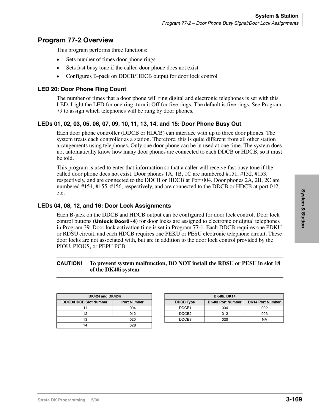
Program 77-2 Overview
LED 20 Door Phone Ring Count
LEDs 04, 08, 12, and 16 Door Lock Assignments
Program 77-3 Overview
Program 77-3 Night Ringing Over Piou External Page Zones
170
Tenant Zone
Program 77-4 Overview
171
Processor Type All RCTUs and BCUs Release 3.2 and above
172
Program 78 CO Line Special Ringing Assignments
173
Program 78 CO Line Special Ringing Assignments
174
Program 78 Overview
175
Program 79 Door Phone Ringing
Program 79 Door Phone Ringing
Ports
176
Program 79 Overview
LED 20 Muted Ring to Busy Electronic and Digital Telephone
LEDs 01~12 Door Phone Ring
Program *79 Overview
Program *79 Door Phone to DN Flashing Assignments
177
Program *79 Door Phone to DN Flashing Assignments
Program 80 EKT and DKT Ringing Tones CO Line Calls
Initialized Default Tone 1 is assigned to all ports
Program 80 Overview
178
Program *80 Call Forward Station Ring Assignment
Initialized Default LED 01, 04, and 07 On for all lines
Program *80 Overview
179
180
Programs 81~89 Ground/Loop Start/CO Line Station Ringing
Programs 81~89 Ground/Loop Start/CO Line Station Ringing
CO Line
Program 81~89 Overview
Ringing Mode Comments
Auto Attendant
Station Ringing Modes
Attendant Console DK424 only
Auto Attendant Delay Ring
182
Attendant Console Load Sharing
Auto Attendant Program Example
183
184
185
Programs *81, *84 and *87 Overview
186
Ground/Loop Start CO Incoming Call Ringing Control
Idle
DN LED
187
188
Program 93 CO Line Identification
Program 93 CO Line Identification
Processor CO Line
Alpha Mode
Numeric Mode
Program 93 Overview
189
Program 97 Printing Program Data through Smdr
Initialized Default Prints out customer database
Program 97 Overview
190
Toll Restriction Methods
Toll Restriction Features
Simple Toll Restriction
Three-digit Toll Restriction
Station Priority Classes 1~8
Special Common Carrier Authorization
Office Code Exception Tables
Toll Restriction Override by System Speed Dial
Completing the Toll Restriction System Record
Completing the Toll Restriction System Record
Program 40 Station CO Line Access
Program 40 Station CO Line Access
Processor Type PDN Port Range Disa Port R3.X
Program 40 Overview
Program 41 Station Outgoing Call Restriction
Program 41 Station Outgoing Call Restriction
Processor CO Line PDN Port Disa Port Range
Processor CO Line PDN Port Disa Port
Program 41 Overview
Trunk Centrex/PBX Connection LED On Normal LED Off
Button Line Set Button LEDs
Program 42-0 Overview
Program 42-1~8 PBX/Centrex Access Codes
Program 42-1~8 PBX/Centrex Access Codes
Initialized Default Assigns no access codes to PBX groups
Program 42-1~8 Overview
Program 43 0 + Credit Card Dialing Option
Program 43 0 + Credit Card Dialing Option
Assigned to allow dial 0+ calls with
Selected stations
Program 43 Overview
Program 44-1~8 Overview
Initialized Default All Classes Blank no code
Toll Restriction Class
Data = 1~4 Digit Code
Program 44-91~93 Overview
Default
Emergency Number 1~3 Data = 1~4 Digit Telephone Number
Select = 91~93 To set Emergency Number 1~3
Program 45-1 Overview
Program 45-1 LCR/Toll Restriction Dial Plan
Plan
Pre-January 1995 North American Numbering Plan Nanp
Plans 4~6
Post 1995 North American Numbering Plan Nanp
Changing System Dialing Plan for Nanp from a Station
Toll Restriction
Plan 7 10XXX+1+NXX+NXX/NXX
Program 45-2 Toll Restriction Disable
Program 45-2 Toll Restriction Disable
Program 45-2 Overview
CO Line Toll
Data =
Program 45-3~6 Overview
Items 4
Items 3
Program 45-8~9 Toll Restriction Override Code
Initialized Default Leaves code assignments blank
Program 45-8~9 Overview
Program 45-8~9 Toll Restriction Override Code
Program *45-1 Overview
Program *45-1 1~4 Toll Restriction for Office Codes
Program *45-1 1~4 Toll Restriction for Office Codes
Data = Office Code
Program *45-2 Overview
Initialized Default All data blank
Example Centrex assume
Program *45-2 1~6 LCR/Toll Restriction Bypass
Example 10-digit Dialing
Program *45-3 Overview
Using or # as the First Digit on Isdn BRI/PRI
Example
LED 01 once
Program *45-4 Overview
Program *45-4 Special Code Dialing Sequence with
LED 01 Pause following Program *45-3 code
LED 02 Order of LCR bypass code and MDT
Program *45-4 LED 02 On LED 02 Off
LCR Example
Program *45-5 Overview
Program *45-5 Overlap Area Code
Program *45-5 Overlap Area Code
Overlap Area Codes 8 max
Program 46-2~4 Overview
Initialized Default Includes all area codes in all classes
Class Check one Allowed Denied Data = Area Codes
Processor Toll Restriction Class
Class Check one Allowed Denied Data = Office Codes
Initialized Default Includes all office codes in all classes
Program 46-6~8 Overview
Programs 46-10~80 Overview
Programs 46-10~80 Toll Restriction Class Parameters
LED 01 0 Restricted
Programs 46-10~80 Toll Restriction Class Parameters
LED 03 1+AC+555 and AC+555 Allowed
LED 02 01 Restricted
Programs 46-11~46-81 Toll Restriction Class 1~8 Parameters
Initialized Default Leaves all LEDs Off
Programs 46-11~46-81 Overview
Programs 46-11~46-81 Toll Restriction Class 1~8 Parameters
Initialized Default Assigns no office codes to tables
Enter only one area code per exception table
Select = Exception ~16
Program 47 Overview
Initialized Default 100 for all ports
Program 48 Station Toll Restriction Classification
Program 48 Station Toll Restriction Classification
Digit Restriction
Program 48 Overview
Station Restriction
Enter Function Description
LCR Features
LCR Conditions
LCR CO Line Programming Reference Table
LCR CO Line Programming Reference Table
Line CO Line in Group CO Line Type/Comments
Processor CO Line Group
Program 50-1 LCR Parameters
LED 01 Enable System LCR
Program 50-1 Overview
LED 02 Not used LED 03 555 LDI Route Per Program
Program 50-2 LCR Home Area Code
LED Button 04 Dial Tone After LCR Access
Program 50-2 Overview
LED Button 05 Warning Tone Last Choice Route Number
Programs 50-3 1~5 LCR Special Codes
Initialized Default 911 in 31, all other codes blank
Programs 50-3 1~5 Overview
Special Code 4 Digits Examples 911 411
Program 50-4 LCR Long Distance Information LDI Plan Number
Processor LDI Route LDI Route Plans Default
Program 50-4 Overview
Data = LDI Route Plan see Legend below
Program 50-5 Overview
Program 50-5 LCR Local Call Plan Number
Select =
Data = Local Call Plan see Legend below
Program 50-6 LCR Dial 0 Zero Time-out
Initialized Default Assigns an LCR Dial Zero Time-out value
Program 50-6 Overview
Overview for Programs 51~54
Processor LCR Plan Number LCR Plan Default
Program 51 LCR Area Codes
LCR Plan Data = Area Codes
Hmis Example
Program 51 Overview
Action Code Function Action Codes
More Data
Processor Table Number LCR Plan LCR Exception
Table Number Area Code LCR Plan Data = Office Codes
Program 52 Overview
Processor Program Program 54 Route
Program 53 LCR Schedule Assignments for LCR Plans
Program Program 54 Route
LCR Plan Schedule Action Start Time 01~16 Code
Installation Requiring Time Scheduling Feature
Typical Installation Without Time Schedule Feature
Program 53 Overview
Least CostRouting
Hotel Administration unrestricted
Guest Room with restricted calling
Guest Room complete restriction/911 only
Program 54 LCR Route Definition Tables
Program 54 Overview
Cost Routing
CO Line Group assigned in Program
Route Definition Number
Modified Digits Table
Local 911 Long Distance
Program 55 LCR Modified Digits Table
Program 55 Series Overview
Processor Modified/Add/Delete
Program 55-0 Overview
Initialized Default All tables blank
Delete Digits Table
Table Number Quantity of Digits 01~10 max
Pause Entry Reference Programs 55-1
Key/LED Pause Seconds Record Entry Special Functions
Table No
Program 55-1 and 2 Overview
Program 56 LCR Station Group Assignments
Initialized Default Assigns all stations to Group
Program 56 LCR Station Group Assignments
Enter LCR Station Group 1~8
Program 56 Overview
Automatic Call Distribution
Automatic Call Distribution
Program 03 RSIU, RSSU, PIOU, Pious ACD/MIS Slot Assignments
Initialized Default n/a
Program 03 Overview
Automatic Call Distribution
Program 09 Auto Attendant Prompt/ACD Group Assignments
Program 09 Auto Attendant Prompt/ACD Group Assignments
Auto ATT Dial = ACD Group Number
Processor ACD Group Numbers
Automatic Call Distribution
Program *09 ACD Group did Line Digit Assignments
Initialized Default See table below
Related Programs
Program *09 ACD Group did Line Digit Assignments
LED 02 Not Used LED 03 Supervisor Monitor Tone and Display
LED 01 Set Next-Available-First or Most-Idle-First Routing
LED 04 ACD Group Unavailable Destination
X column is checked, the LED should be On
Program 11 ACD Timing Assignments
Program 11 ACD Timing Assignments
Call Distribution
Data = Time min. or sec
Code 3 After Call Work Timer
Code 2 Ring Agent Timer
Code 4 Ring-Back-Tone RBT Timer
Program 11 Overview
Code 6 Call Waiting Alarm Timer
Code 5 Music Timers 1, 2,
Code 7 Call Waiting Alarm Timer
Code 8 Alarm Guard Timer
Code 9 Call Disconnect Timer
Light Button/LEDs of CO lines that should be
Program 14-0 Overview
ACD Group Number Assigned to the ACD Group
Processor ACD Group CO Line Range
Program 14-1 Overview
Program 14-1 ACD Agent Identification Code Assignments
Program *14-1 Overview
Program 14-1 ACD Agent Identification Code Assignments
Program 18 Agent Names for SMIS/MIS Assignments
Program 18 Overview
Program 18 Agent Names for SMIS/MIS Assignments
Alpha Entry Example Special Character Entry
Alpha Mode
Initialized Default All blanks
Program 14-2 ACD Supervisor Passwords
Program 14-2 ACD Supervisor Passwords
Program 14-2 Overview
Select = ACD Group Number
Initialized Default Port
DID/Tie/DNIS/ANI Overflow Substitution Destination
DID/Tie/DNIS/ANI Overflow Substitution Destination
Program *14-2 Overview
Program 14-3 Announcement/Music Port and Queue Pattern
Program 14-3 Announcement/Music Port and Queue Pattern
Program 14-3 Overview
ACD Queue Announcement and Music Patterns
Data = Queue Timeout Overflow Destination
Program 14-4 Queue Time Out Overflow Destination
Program 14-4 Queue Time Out Overflow Destination
Program 14-4 Overview
Data = Destination
Initialized Default Overflow point = 0 no overflow point
Processor ACD Group Numbers PDN Port Range PhDN Port Range
Data Overflow Point and Ring No Answer Routing Destination
Program 14-5 Overview
Call Queue Overflow Point OP Guide
Overflow Operation
Non-Repeating Queue Announcement
Program 14-6 After Shift Service Destination
Program 14-6 After Shift Service Destination
Initialized Default Destination = Incoming port
Data = Destination
Program 14-6 Overview
Initialized Default Queue Size =
Program 14-71 Queue Size for Alarm, Immediate Assignments
Program 14-71 Queue Size for Alarm, Immediate Assignments
Program 14-71 Overview
Program 14-72 Queue Size for Alarm
Program 14-72 Queue Size for Alarm
Program 14-72 Overview
Select = ACD Group No
Program 14-73 Queue Size for Alarm
Program 14-73 Queue Size for Alarm
Program 14-73 Overview
Data = Queue Size
Data = 0 No Alarm
Program 14-8 Alarm Pattern Assignments
Data = 1 Immediate Alarm
Data = 2 Call Waiting Alarm 1
Automatic Call Distribution
Program 14-9 Work Unit Assignments
Initialized Default account digits for each Group =
Program 14-9 Overview
Program 14-9 Work Unit Assignments
Also see Program 17 DID/Tie Line Options on
Program 71 DID/Tie/DNIS/ANI Lines
ACD Feature Button Program Program on
Program 39 Flexible Button Assignments for ACD Telephones
Program 39 Flexible Button Assignments for ACD Telephones
Call
PhDN like Agent telephones
This is the PDN of the Supervisor telephone
Supervisors with Busy Station Ring see Program
BST and BSR
Agent and Supervisor Telephone Programming Considerations
Related Programs
Possible ways to route CO line calls to ACD group
Flowchart 6-1 ACD Group Call Routing
Flowchart 6-2 ACD Group Queue/Overflow Operation
Automatic Call
Distribution
DNIS/ANI?
Flowchart 6-3 ACD Time Out Overflow
Agent ACD Call button idle in the group?
Flowchart 6-4 ACD Overflow Point
End of ACD Shift Conditions
Flowchart 6-5 After Shift Operation
LED 04 OFF
Flowchart 6-6 All Agents Unavailable Operation
Button Ring system DN, DH, or Console port assigned
Flowchart 6-7 Agent Telephone Ring No Answer Operation
Start call enters queue from ACD Flowchart
Start call enters queue from ACD Flowchart
Two announcements, then music
ACD Queue Pattern Configuration Two Announcements
Music source
System Programs Overview
Isdn
System Programs Overview
Flowchart
Isdn Related Programs
Isdn Related Programs
PRI
Flowchart 7-2 Isdn Trunk Programs
Trunk Programs Overview
Primary Rate Interface PRI Programming
Trunk Programs Overview
Programming for Isdn CO Switch Type
Guidelines for Programming Isdn Calling Features
Guidelines for Programming Isdn Calling Features
Programming for Isdn PRI did Type Call
Did number
LEDs 01-02
Programming for Isdn PRI Dnis Type Call
68-1
71-0
Isdn PRI Dnis Type Call Programming
Programming for Isdn PRI LDN Type Call
Program Program Data Description Number
71-1
Call-By-Call Overview
T1 Example
T1 Channel Group
Call-by-Call Line Sharing
Channel Group
Call-by-Call Min/Max Control
Call-by-Call Programming
Time Zones
0000 0600 1200 1800 2359 Channel Group Time Zone
Time Zones
Program 16 Assign CO Line Groups
Program 16 Assign CO Line Groups
Program *16 Isdn Trunk Group Type Assignment
Initialized Default Type 1 non-ISDN
Program *16 Overview
Trunk Groups
Program *42 Clock Source
Program *42 Series Overview
Program *42 Clock Source
Program *43-1~3 Overview
Program *43-1~3 D-Channel Control and Nfas Assignments
Program *43-1 Overview
Program *43-1~3 D-Channel Control and Nfas Assignments
Program *43-2 Overview
Initialized Default Blank see Note and Important! below
Guide to Programming Nfas with Release 4.15 software
01 or
Program *43-3 Network PRI Interface Assignment
Initialized Default LED 01 On
Program *43-4 PRI Explicit/Implicit Coding Assignment
Program *43-3 Overview
Program *44 BRI Service Profile Identifier Spid Parameters
Program *44 BRI Service Profile Identifier Spid Parameters
Program *44 Overview
BRI Trunk Number Spid Type Spid Value
Program *60 Overview
Program *60 BRI Line/Station Operation Assignment
Program *60 BRI Line/Station Operation Assignment
LEDs Slot
Initialized Default See below
Program *61 Analog Trunk Services for Isdn
Program *61 Analog Trunk Services for Isdn
Program *61 Overview
Program *62 Non-ISDN Station Bearer Service
Program *62 Non-ISDN Station Bearer Service
Outgoing Incoming Station Ports Service Pad Level
Program *62 Overview
Program *63 Isdn Dialing Parameters
Initialized Default 4 seconds
Program *63 Overview
Program *63 Isdn Dialing Parameters
Program *64-1 Overview
Program *64-1 Direct Inward Dialing Parameters
Program *64-1 Direct Inward Dialing Parameters
Trunk Ports LEDs Groups
Program *64-2 Number of DID/DNIS Digits for Trunk Groups
Program *64-2 Overview
Program *64-2 Number of DID/DNIS Digits for Trunk Groups
Program *65 Isdn Channel Group Assignment
Initialized Default All Leds Off see Important! below
Program *65 Overview
Program *65 Isdn Channel Group Assignment
Program *66-1 Overview
Program *66-1 Channel Group Number Parameters
Program *66-1 Channel Group Number Parameters
SEL = Enter the Isdn Trunk Group Number
Program *66-2 Overview
Program *66-4 Overview
Program *66-4 Call-by-Call Network ID
Record Sheet
Enter Isdn Trunk Group Number
LEDs Setting Trunk Groups
LEDs 11, 13, 14, 15 Programming for Isdn CO Switch Type
Program *66-3 Channel Group/Trunk Parameters
Program *66-3 Overview
Program *66-4 Call-by-Call Network ID
Program DMS 100 Custom Switch NI-2 Switches
Program *66-5 Line Directory Number LDN Registration
Program *66-5 Overview
Program *66-5 Line Directory Number LDN Registration
Program *66-6 Overview
Program *66-6 LDN/Trunk Group to Channel Group Assignments
For Programs *66-5 and *66-6
Program *66-6 LDN/Trunk Group to Channel Group Assignments
Program *66-7 Overview
Program *66-7 LDN/Trunk Group Assignments
Program *66-7 LDN/Trunk Group Assignments
Channel
Program *67-1 Trunk Group Call Direction
Initialized Default Both Way
Program *67-1 Overview
Program *67-1 Trunk Group Call Direction
Program *67-2 Call Types for Isdn Trunk Group Supported
Program *67-2 Overview
DK40i, all RCTUs Release 4.0 or higher and BCUs
Trunk, PRI
Program *67-3 Isdn Trunk Group Minimum Channel Reservation
Initialized Default Default =
Program *67-3 Overview
Trunk Time Zone Channels reserved
Program *67-4 Isdn Trunk Groups Maximum Channel Reservation
Program *67-4 Overview
Program *67-4 Isdn Trunk Groups Maximum Channel Reservation
Program *67-5 Multiple Time Zone Settings
Program *67-5 Multiple Time Zone Settings
Program *67-5 Overview
Enter the Time Zone Starting. Time 0000~2359
Program *68-1 Overview
Program *68-1 Calling Number ID Presentation Parameters
LED 01 Outgoing Caller ID
LED 02 Outgoing Caller ID Status Change
Program *68-2 Overview
Program *68-2 Outbound Cnis Parameters
Program *68-2 Outbound Cnis Parameters
Trunk Groups Calling Party Number
Program *69-1 Overview
Program *69-1 Cnis Presentation Parameters
Program *69-1 Cnis Presentation Parameters
Station Ports Channel Index Group
Program *69-2 Overview
Program *69-2 Special Number Assignment
Program *69-2 Special Number Assignment
Index Type Calling Party Number
E911
Operation Overview
Smdr Start of Call
E911
Programming Overview
Programming Overview
LED 10~07 Cama Trunk Circuits Enabled/Disabled
LED 11 Cama Operation Enabled/Disabled
LED 03 Internal Notification of E911 Calls Enabled/Disabled
Program *11-0 E911/CAMA Trunk Assignments
LED 01 Number of Cesid location digits sent with E911 Calls
LED 02 Cama Trunk Disconnect Operation Options
Program *11-1 Overview
Program *11-1 Cama Trunk Group Line Assignments
Program *11-1 Cama Trunk Group Line Assignments
Cama Trunk Group 01~08
Program *11-2 Overview
Program *11-2 Cama Trunk Group Hunting Assignments
Program *11-2 Cama Trunk Group Hunting Assignments
Hunt from Cama Hunt to Cama Trunk Trunk Group
Program *11-5 Cama Digits Sent on 911 Calls
Program Type System Initialized Default
Program *11-5 Overview
Program *11-5 Cama Digits Sent on 911 Calls
Program Type System Initialized Default Data, 2 seconds
Program *11-6 E911 Interdigital Timer
Program *11-6 E911 Interdigital Timer
Program *11-6 Overview
Mode DN Port Number
Program Type System Initialized Default Data, Blank
Program *11-8 911 Special DN Notification Assignments
Program *11-8 Overview
Program *12 Cesid Station Information
Program Type System Initialized Default Data Blank
Program *12 Overview
Program *12 Cesid Station Information
E911
Program *13 Overview
Program *13 Station To Cama Trunk Group Assignment
Program *13 Station To Cama Trunk Group Assignment
E911 Station Cama Trunk Group Number 01~08
E911
Term Definition
Amphenol Connector
B5CAU/BU B-channel
Bps
GL-2
DK DKAdmin DKBackup
Glossary
Clid or CND CO Line CODECs
DKT2000 series ~ Hdss
DKT2000 series
DKSUB280 or DKSUB424 DKSUE280 or DKSUE424
GL-4
NT-1
GL-5
PhDN
GL-6
GL-7
Rpsb 1
GL-8
Interface
R48S
GL-10
T1/DS-1
Interface Universal slot
Index
IN-1
Index
IN-2
~ P
IN-3
10Program *12
IN-4
IN-5
IN-6
~ R
IN-7
IN-8