STUDIO160/200/250
All rights reserved
Toshiba TEC Corporation
Transportation
Installation
Service of Machines
Disposition of Consumable Parts/Packing Materials
Main Service Parts for Safety
Contents
Other service call Troubleshooting of Image
Maintenance Performed Every 81,000 e-STUDIO160/200 Series
Troubleshooting Based on Error Code
Wire Harness Connection Diagrams
Page
Error Code List
Adjustment Items
EA1
Radf
EA2
EA3
December 2002 Toshiba TEC STUDIO160/200/250 Adjustment Items
Radf
CA2
CA1
CB1
CB2
After entering Service Mode
Maintenance
Self-Diagnosis Modes
Function
Power OFF Turn on the power switch
Turn on the power switch
INT
Press the Interrupt key
Cancel Adjustment value
Adjustment value Enter code
SET Start
Display messages
Process unit adjustment
Adjust Mode 05 Items
Printer adjustment
Scanning adjustment
Scan image processing parameter 600 DPI
Use of default value Larger the intensity Text/Photo mode
Cancel
Setting value Enter code
System Mode 08 Items
Setting value
Maint
Mode 375
Print
NON Sort 1 Staple 2 Sort
Auto Test
Completed
Program
Individual Test
SET
SET CIS
Select Test Result List Use or keys
Select Test Mode
Test Result List
Modem Test *1 Factory test
Following tests can be conducted in the Function test mode
OPE. Panel Test Print Test
Cursor moves from the upper left to the lower right
OPE Panel Test
Digital Keys Print setup 2 B
Digital Keys Print setup 1 T
Digital Keys Select paper cassette C
Print code
Test Print 02 Items
Sensor Test
Display selection Cancel Display messages
BIT
12 S1
IO4 Bit2
Display is switched using the or key Status display example
PFC
With bits 4 and 5 of IO1 Bit7 Bit6
PWA
IO1 IO1
MEM1DET
Sensor Test 04 Items
Bucs
16MBDET
Sizpfu
EXIT-SW
Cancel Display messages
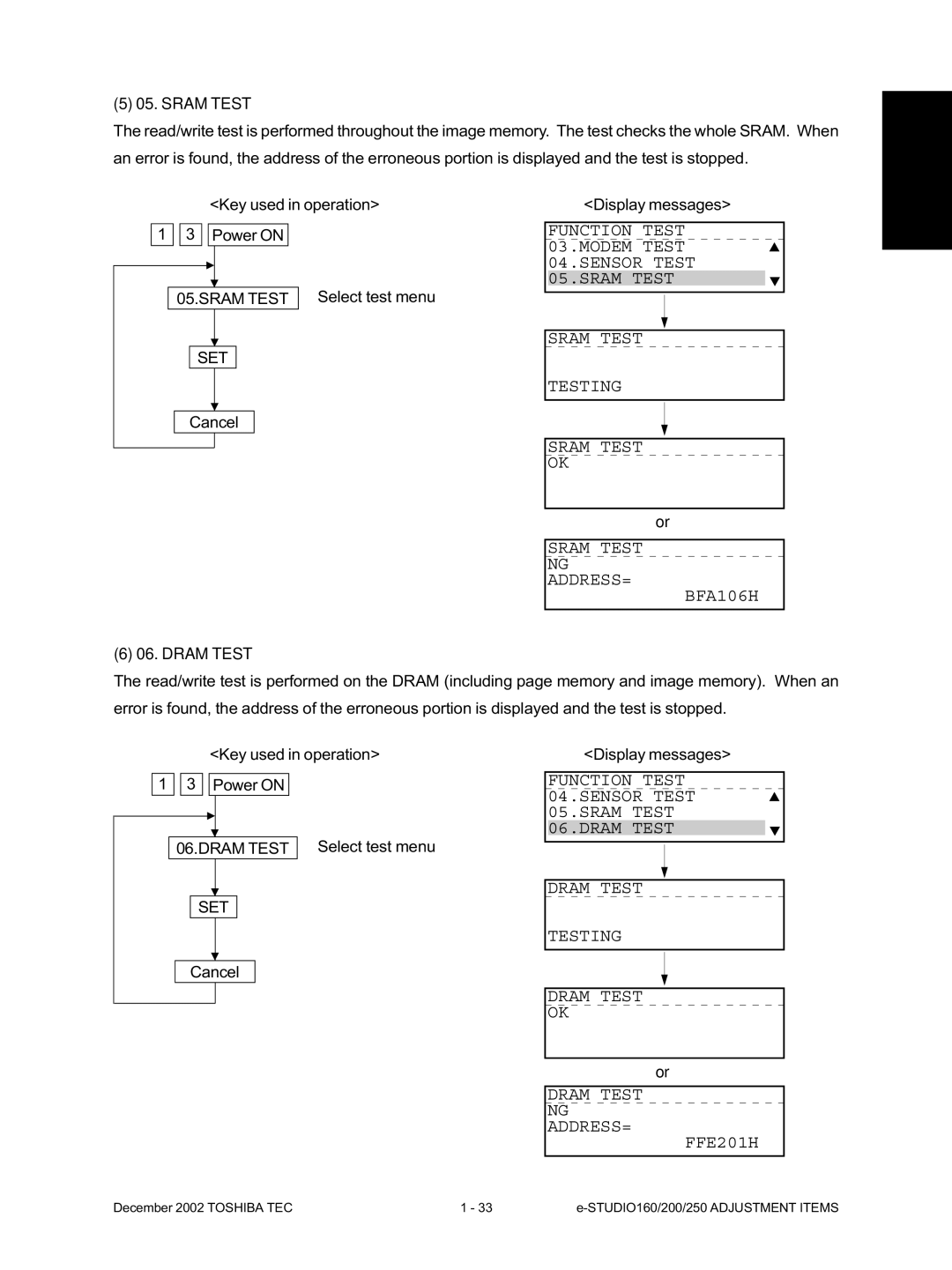
Function Test 06.DRAM Test 07.CLOCK IC Test 08.SCANNER Test
Test start Test stop
Digital Keys Enter test mode Test code
Select test menu
Output Test 10 Items
Page
Maintenance Memory Clear
End of test Cancel Display messages
Printer Board Test
Warming up Ready Standby
Item selection from menu Key used in operation
Select Maintenance Use or keys
Select Memory Clear Use or keys
Select menu
Func
RAM clear table
December 2002 Toshiba TEC STUDIO160/200/250 Adjustment Items
Error Counter Shift
Cancel SET
SET Function
Memory Write
Drum History
Service List
Protocol Trace *1 Total Errors *1
Protocol Trace
Total Errors
COUNTRY/REGION
Country/Region code
Total Print
Current Counter
Drum Counter
History
Address
Memory Dump List
Memory dump start address. The last digit is always 0. *1
HEX Ascii
Print list
Select Lists
Select Function Use or keys
Document
JAM Counter
Paper JAM
TYPE1 JAM
ASD/AUD/CND/SAD/MJD
NAD
Test Mode PA
Select Machine Default Use Keys
Select Default Setting Use Keys
Adjust the volume Use Keys
Use Keys
Adjust the document guide to the widest Enter code
SET Cancel
Code Set the value Test print
Image Quality Control
SET INT Start
Copy Image Dimension Adjustment
Digital Keys SET INT Start INT Set the value or Test copy
Power on Code
Main Menu Interrupt SET
Interrupt Program 05TEST Mode SET
04FUNCTION Test SET 02PRINT Test
Main Menu Interrupt
5C15
Adjust the installed option units
Registration Adjustment order
443
LCF
Copy movement direction 100
Copied scale Copy movement direction Actual scale
01-04-10
Code Set the value Test copy
Power on Code Set the value
Enter code Set the value
Sharpness HPF Adjustment
Code Default value 620 621 622
Gamma Slope Correction
000
High-Voltage Adjustment
Door switch jigs Door switch jig Large Door switch jig Small
SET Value YYY after adjustment is stored to SRAM. or
Current entried adjustment value
Start Cancel
Return to other adjustment mode Power OFF
December 2002 Toshiba TEC STUDIO160/200/250 Adjustment
Copy trailing edge
Copy leading edge Copy trailing edge
Adjusting the Scanner Section
Tab Stopper Original glass
Scanner motor
Roller Holding part Lamp cable Carriage
057-3-1
Wire Scanner drive shaft
Rear Side Front Side
Relationship between wound turns and wire holder jigs
CCD unit Replacing the CCD unit
CCD Jig CCD unit
065-04-2
065-04-3
Adjusting the main drive gear assembly
Release the jam lever of the fuser
Main motor Gear Fuser Jam lever
Plate Screw a Main drive gear assembly Collar
CND SET
Main PWA replacement procedure
Initial Setup Date & Time
December 2002 Toshiba TEC STUDIO160/200/250 Adjustment Items
Measurement of Transfer Guide Bias
Output Test SET Start Cancel
Display messages and measurement methods
Enter the Transfer Guide Bias ON/OFF code
Power OFF To measure on the paper guide plate
CLEAR/STOP Cancel
From preceding
Turn the transfer guide bias OFF End the output test
Adjustment of the doctor-sleeve gap
Symbols used in the check list
Preventive Maintenance Check List
Page
Main Rear view
Fuser unit Pressure roller
Check
Doctor blade cleaning jig Magnetic roller
Drive gear
HR drive gear Boss
Page
MY-1015
MD-0101
MR-3011
MY-1016
MJ-5002
MJ-5001
KD-1010
KD-1009
MR-2012
PM Kit
List of Grease
List of Adjustment Tools
Precautions for Storing Toshiba Supplies
Precautions for Storing & Handling Supplies
Checking and Cleaning of the Cleaning Roller
Checking and Cleaning of the Pressure Roller
Checking and Replacing of the Transfer Guide Roller
Checking and Cleaning of the Heat Roller
Checking and Cleaning of the Photoconductive Drum
Checking and Cleaning of the Drum Cleaning Blade
Troubleshooting
YES
Troubleshooting Based on Error Code
YES
YES
YES
YES
YES
YES
YES
PWA CN36 is disconnected
PWA CN205 is disconnected
Open- or short-circuited
Replace the 2nd feed roller clutch
YES
YES
YES
YES
YES
YES
YES
YES
YES
YES
YES
Replace the rollers
Set only one-size originals Is the separation pad stained?
YES
YES
Clean the rollers Is the reverse flapper working properly?
EA2
Remove the paper Is the finisher connected to the main unit?
EA5
EA7
STUDIO160/200/250 Troubleshooting December 2002 Toshiba TEC
YES
YES
YES
YES 1
YES
YES
YES
YES
YES
STUDIO160/200/250 Troubleshooting December 2002 Toshiba TEC
Replace the main PWA
STUDIO160/200/250 Troubleshooting December 2002 Toshiba TEC
December 2002 Toshiba TEC STUDIO160/200/250 Troubleshooting
YES
YES
Radf
December 2002 Toshiba TEC STUDIO160/200/250 Troubleshooting
STUDIO160/200/250 Troubleshooting December 2002 Toshiba TEC
YES
YES END
CC8
CC9
CCA
CCB
YES
STUDIO160/200/250 Troubleshooting December 2002 Toshiba TEC
December 2002 Toshiba TEC STUDIO160/200/250 Troubleshooting
Feeding direction
Troubleshooting of Image
Uneven pitch and blur Symptoms
Replace registration roller
Blurred image Feeding direction
Re-install transfer charger unit securely
Solid copy Feeding direction
White banding in feeding direction Feeding direction
Minals main body stained? Transfer charger unit
Black banding in feeding direction Feeding direction
Main charger Formed? Or charger wire
White Spots Feeding direction
Uneven image density Feeding direction
Blotched image Feeding direction
Poor image transfer Feeding direction
Poor cleaning Feeding direction
Hvps
Background Fogging Feeding direction
Toner offset
Poor fusing Feeding direction
Defect of image density/Gray balance
Lack of sharpness
Moire/lack of sharpness Feeding direction
Uneven light distribution Feeding direction
Skew inclined image Feeding direction Moire
Image dislocation in feeding direction Feeding direction
Jittering image Feeding direction
Outline
Updating the Firmware
Turn off the power Remove the rear cover
Using the Recovery PWA
Main PWA Main recovery PWA CN10
Page
Connector Scanner recovery PWA
Remove the blind plate
Page
MKRPCDSK.BAT DISK.EXE
Using the Batch File
Press the Enter key. Formatting of Disk 1 begins
MS-DOS prompt screen shows the following
Type mkrpcdsk and press the Enter key
Download program is copied to Disk
When formatting is completed, the following screen appears
Press the Enter key Type n and press the Enter key
Press the Enter key Formatting of Disk 2 begins
05-03-014
05-03-016
When copying is completed, the following screen appears
05-03-019
LCD display on the copier
05-03-022
05-03-023
When downloading ends, the following screen appears
Using the Toshiba Viewer
Page
Page
Page
Wire Harness
Wire Harness Connection Diagrams
Connector Table
LT-R
Appendix A. Specifications
PFU PFP LCF
LD ST-R, COM
Sette, 100%, original placed manually
STUDIO160 series Less than 7.9 seconds A4/LT, the Upper cas
STUDIO200 series Less than 7.0 seconds A4/LT, the Upper cas
STUDIO250 series Less than 7.0 seconds A4/LT, the Upper cas
Weight
Appendix B. Accessories
Appendix C. Options
Appendix D. Replacement Units/Supplies
Fig. E-1
Appendix E. System List
Appendix F. Power Supply Unit
5VPS
24VSW
+24 24VFU2 24VFU1 12V +12
Kanda NISHIKI-CHO, CHIYODA-KU, TOKYO, 101-8842 Japan