1.10 MAIN PWA replacement procedure
1.Downloading of the MAIN PWA firmware
For details, see chapter 5 of the Service Handbook.
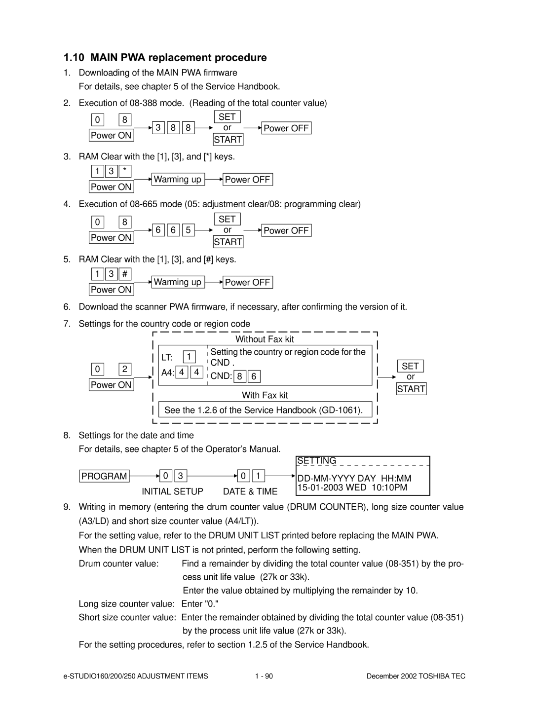
2.Execution of
0 | 8 |
|
|
|
|
|
|
| SET |
|
|
|
|
| |||
|
|
|
| 3 8 | 8 |
|
|
|
|
| or |
|
| Power OFF | |||
|
|
|
|
|
|
|
| ||||||||||
| Power ON |
|
|
|
|
|
|
| START |
|
|
|
| ||||
|
|
|
|
|
|
|
|
|
|
|
|
|
| ||||
3. RAM Clear with the [1], [3], and [*] keys. |
|
| |||||||||||||||
1 3 | * |
|
|
|
|
|
|
|
|
|
|
|
|
|
|
| |
|
|
|
|
| Warming up |
|
|
| Power OFF |
| |||||||
|
|
|
|
|
|
|
| ||||||||||
| Power ON |
| |||||||||||||||
|
|
|
|
|
|
|
|
|
|
|
|
|
|
|
| ||
4. Execution of
0 | 8 |
|
|
|
|
|
|
| SET |
|
|
|
|
| |||
|
|
|
| 6 6 | 5 |
|
|
|
|
| or |
|
| Power OFF | |||
|
|
|
|
|
|
|
|
|
| ||||||||
| Power ON |
|
|
|
|
|
|
| START |
|
|
|
| ||||
|
|
|
|
|
|
|
|
|
|
|
|
|
| ||||
5. RAM Clear with the [1], [3], and [#] keys. |
|
| |||||||||||||||
1 | 3 # |
|
|
|
|
|
|
|
|
|
|
|
|
|
|
| |
|
|
|
|
| Warming up |
|
|
|
| Power OFF |
| ||||||
|
|
|
|
|
|
|
|
| |||||||||
| Power ON | ||||||||||||||||
|
|
|
|
|
|
|
|
|
|
|
|
|
|
|
| ||
6.Download the scanner PWA firmware, if necessary, after confirming the version of it.
7.Settings for the country code or region code
|
|
|
|
|
|
|
|
|
|
|
|
|
|
|
|
|
|
|
|
|
|
|
|
|
|
|
|
|
|
|
|
|
|
|
|
|
|
|
|
|
|
|
|
|
|
|
|
|
|
|
|
|
|
|
|
|
|
|
|
|
|
|
|
|
|
|
|
|
|
|
|
|
|
|
|
| Without Fax kit |
|
|
|
| ||||||||||||||||||||||||||||
|
|
|
|
|
|
|
|
|
|
|
|
|
|
|
|
|
|
| ||||||||||||||||||||||||||||||||||||
|
|
|
|
|
|
|
|
|
|
|
|
|
|
|
|
|
|
|
|
| ||||||||||||||||||||||||||||||||||
|
|
|
|
|
|
| LT: | 1 |
|
|
|
| Setting the country or region code for the |
|
|
|
|
| ||||||||||||||||||||||||||||||||||||
|
|
|
|
|
|
|
|
|
|
|
|
|
|
|
| |||||||||||||||||||||||||||||||||||||||
|
|
|
|
|
|
|
|
|
|
|
|
|
|
|
|
| ||||||||||||||||||||||||||||||||||||||
|
|
|
|
|
|
|
|
|
|
| CND . |
|
|
|
|
|
| |||||||||||||||||||||||||||||||||||||
0 | 2 |
|
|
|
|
| A4: | 4 4 |
|
|
|
|
| SET |
| |||||||||||||||||||||||||||||||||||||||
|
|
|
|
|
| CND: |
|
|
|
|
|
|
|
|
|
|
|
|
|
|
|
|
|
|
|
|
|
|
|
|
|
|
|
|
|
|
|
| ||||||||||||||||
|
|
|
|
|
|
|
|
| 8 |
| 6 |
|
|
|
|
|
|
|
|
|
|
|
|
|
|
|
| or | ||||||||||||||||||||||||||
|
|
|
|
|
|
|
|
|
|
|
| |||||||||||||||||||||||||||||||||||||||||||
Power ON |
|
|
|
|
|
|
|
|
|
|
|
|
|
|
|
|
|
|
|
|
| With Fax kit |
|
|
|
| START | |||||||||||||||||||||||||||
|
|
|
|
|
|
|
|
|
|
|
|
|
|
|
|
|
|
|
|
|
|
|
|
|
| |||||||||||||||||||||||||||||
|
|
|
|
|
|
|
|
|
|
|
|
|
|
|
|
|
|
|
|
|
|
|
|
|
| |||||||||||||||||||||||||||||
|
|
|
|
|
|
|
|
|
|
|
|
|
|
|
|
|
|
|
|
|
|
|
|
|
|
| ||||||||||||||||||||||||||||
|
|
|
|
|
|
| See the 1.2.6 of the Service Handbook |
|
|
|
|
|
| |||||||||||||||||||||||||||||||||||||||||
|
|
|
|
|
|
|
|
|
|
|
| |||||||||||||||||||||||||||||||||||||||||||
|
|
|
|
|
|
|
|
|
|
|
|
|
|
|
|
|
|
|
|
|
|
|
|
|
|
|
|
|
|
|
|
|
|
|
|
|
|
|
|
|
|
|
|
|
|
|
|
|
|
|
|
|
|
|
|
|
|
|
|
|
|
|
|
|
|
|
|
|
|
|
|
|
|
|
|
|
|
|
|
|
|
|
|
|
|
|
|
|
|
|
|
|
|
|
|
|
|
|
|
|
|
|
|
|
|
|
|
|
|
|
|
|
|
|
|
|
|
|
|
|
|
|
|
|
|
|
|
|
|
|
|
|
|
|
|
|
|
|
|
|
|
|
|
|
|
|
|
|
|
|
|
|
|
|
|
|
|
|
|
|
|
|
|
|
8.Settings for the date and time
For details, see chapter 5 of the Operator's Manual.
|
|
|
|
|
|
|
|
|
| SETTING |
|
|
|
|
|
|
|
|
|
|
|
|
|
|
| |||||||||||||
|
| 0 |
|
|
|
|
|
|
|
|
|
|
|
|
|
|
|
|
|
|
|
|
|
|
|
|
|
|
|
|
|
|
|
|
|
|
|
|
PROGRAM |
| 3 |
|
| 0 | 1 |
|
|
|
|
| HH:MM | ||||||||||||||||||||||||||
|
|
|
| |||||||||||||||||||||||||||||||||||
| INITIAL SETUP | DATE & TIME |
|
|
|
| 10:10PM | |||||||||||||||||||||||||||||||
|
|
|
|
|
|
|
|
|
|
|
|
|
|
|
|
|
|
|
|
|
|
|
|
|
|
|
|
|
|
| ||||||||
9.Writing in memory (entering the drum counter value (DRUM COUNTER), long size counter value (A3/LD) and short size counter value (A4/LT)).
For the setting value, refer to the DRUM UNIT LIST printed before replacing the MAIN PWA.
When the DRUM UNIT LIST is not printed, perform the following setting.
Drum counter value: | Find a remainder by dividing the total counter value |
| cess unit life value (27k or 33k). |
| Enter the value obtained by multiplying the remainder by 10. |
Long size counter value: Enter "0."
Short size counter value: Enter the remainder obtained by dividing the total counter value
For the setting procedures, refer to section 1.2.5 of the Service Handbook.
1 - 90 | December 2002 TOSHIBA TEC |